Glowtie
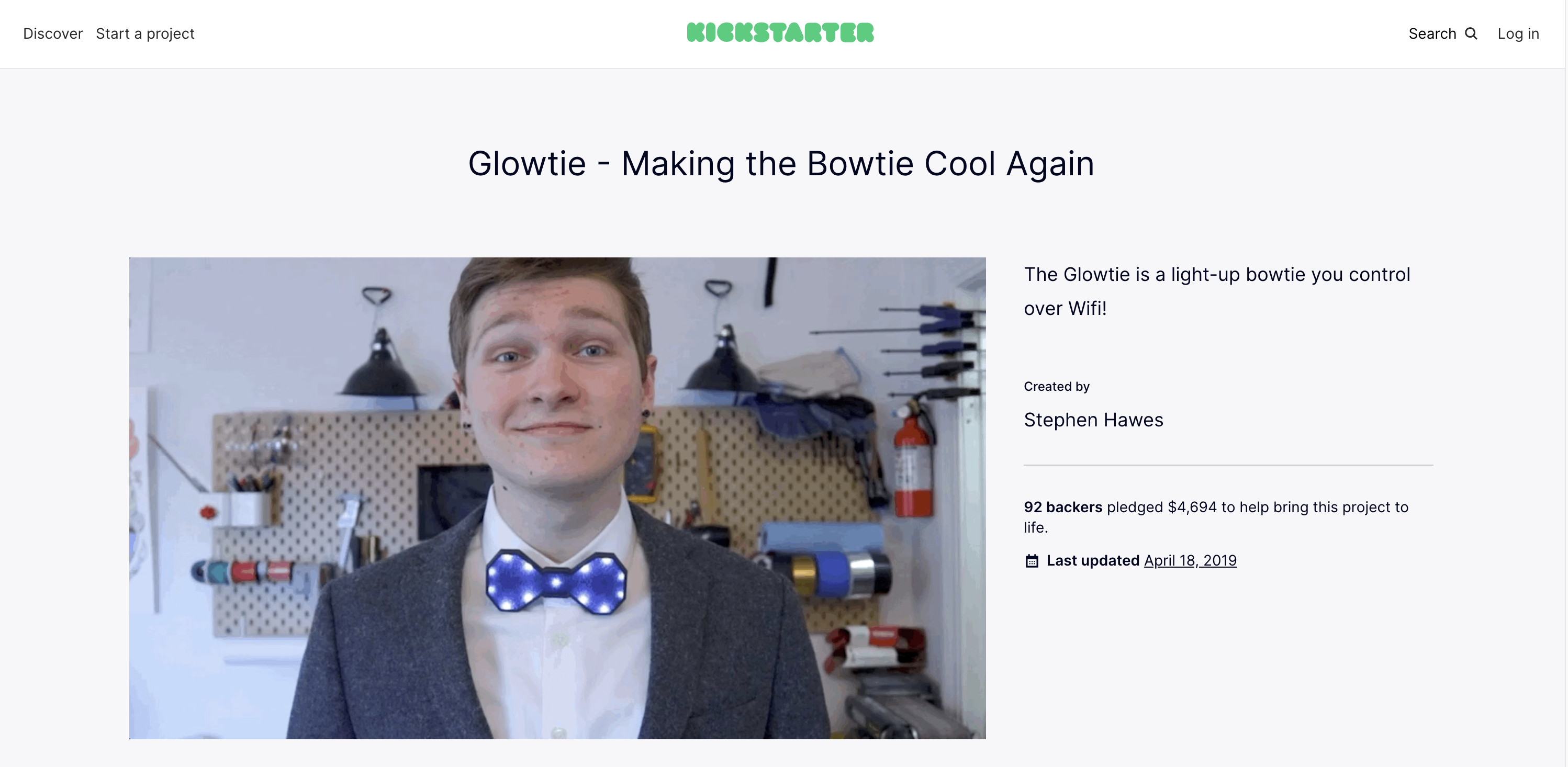
The Glowtie is a light up bowtie that’s controlled using Wifi!

In February 2019, I launched a Kickstarter for this project and raised 234% of my goal. In September 2019 I finished shipping.
Design
I made a 3D printed bowtie for my grandpa a few years back. It had a little slot in the back that let you slide it over your top button, and he got a huge kick out of it.
 Two of my uncles, my grandpa, and my dad all wearing 3D printed bowties.
So I decided to kick it up a notch and do one that lights up! This was also my foray into PCB design, so I was using this project as an opportunity to gain a new skill. I figured adding a physical button or joystick interface for controlling the bowtie would be a bit clunky, so I decided to use the increasingly popular ESP8266 Wifi chip to provide the UI. I wanted the bowtie to put out its own Wifi hotspot, so you can connect with your phone and open a webpage hosted by the tie to control the patterns and colors of the lights. I wanted the tie to be rechargeable, so I used the gloriously open source designs of Adafruit’s Micro Lipo charger as reference for my charging circuit. This will recharge two 1S lipo batteries (in parallel) mounted to the back of the board, and encased in a 3D printed frame that also has the button slot integrated in it.
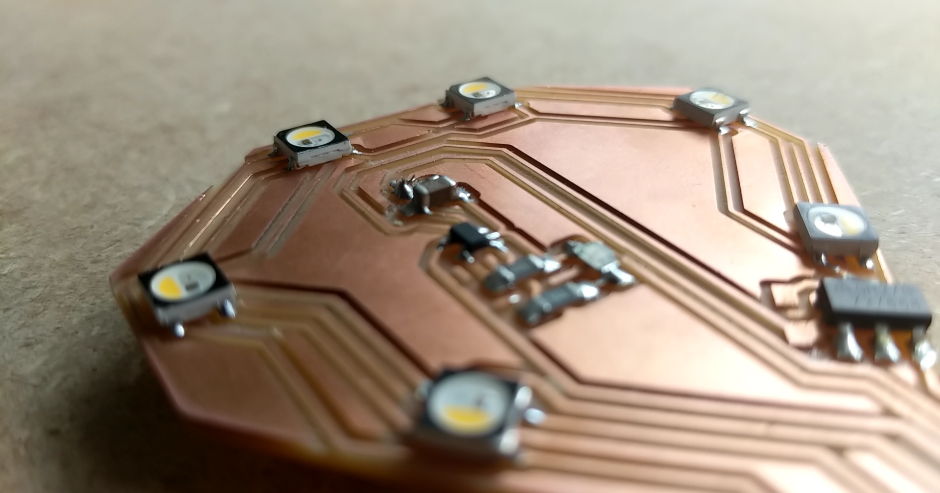
I’m using WS2812B individually addressable RGB LEDs. These are awesome little lights with actual tiny microcontrollers embedded in each LED! It’s a one-wire protocol, and pretty much anything can talk to them. However, they’re designed to work at 5v, but the ESP module I’m using is 3.3v only, and in order to provide 5v from the lipos I’m using, I would also need a boost converter (as opposed to just an LDO) which would significantly complicate the circuit, and make production more expensive. So I went poking through the datasheet, and the minimum supply voltage was actually 3.5v! Turns out they added a bit of buffer to the datasheet, because they lit right up at 3.3v.
I designed a test circuit in KiCad and milled it out on a Bantam Tools desktop mill.
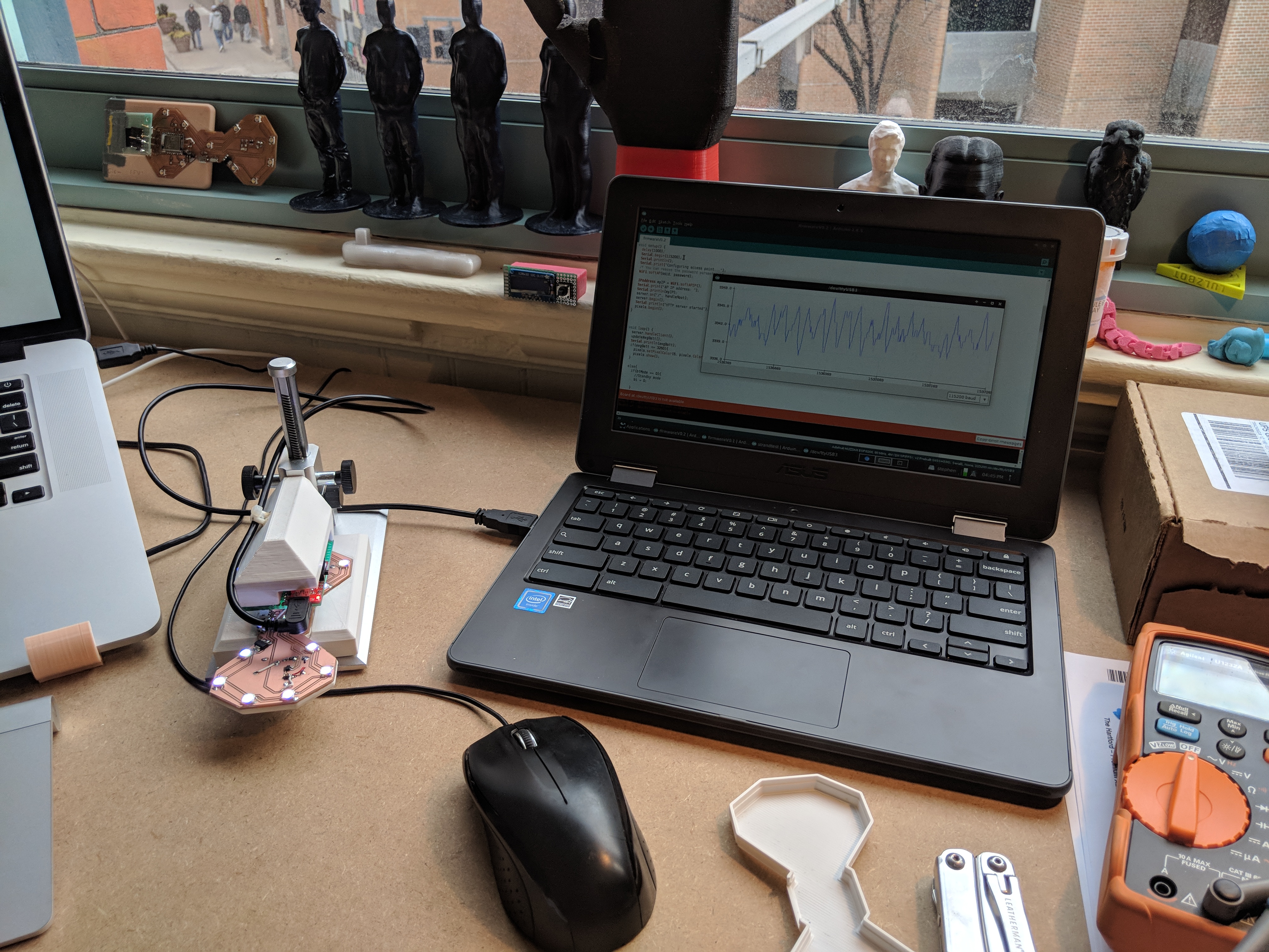
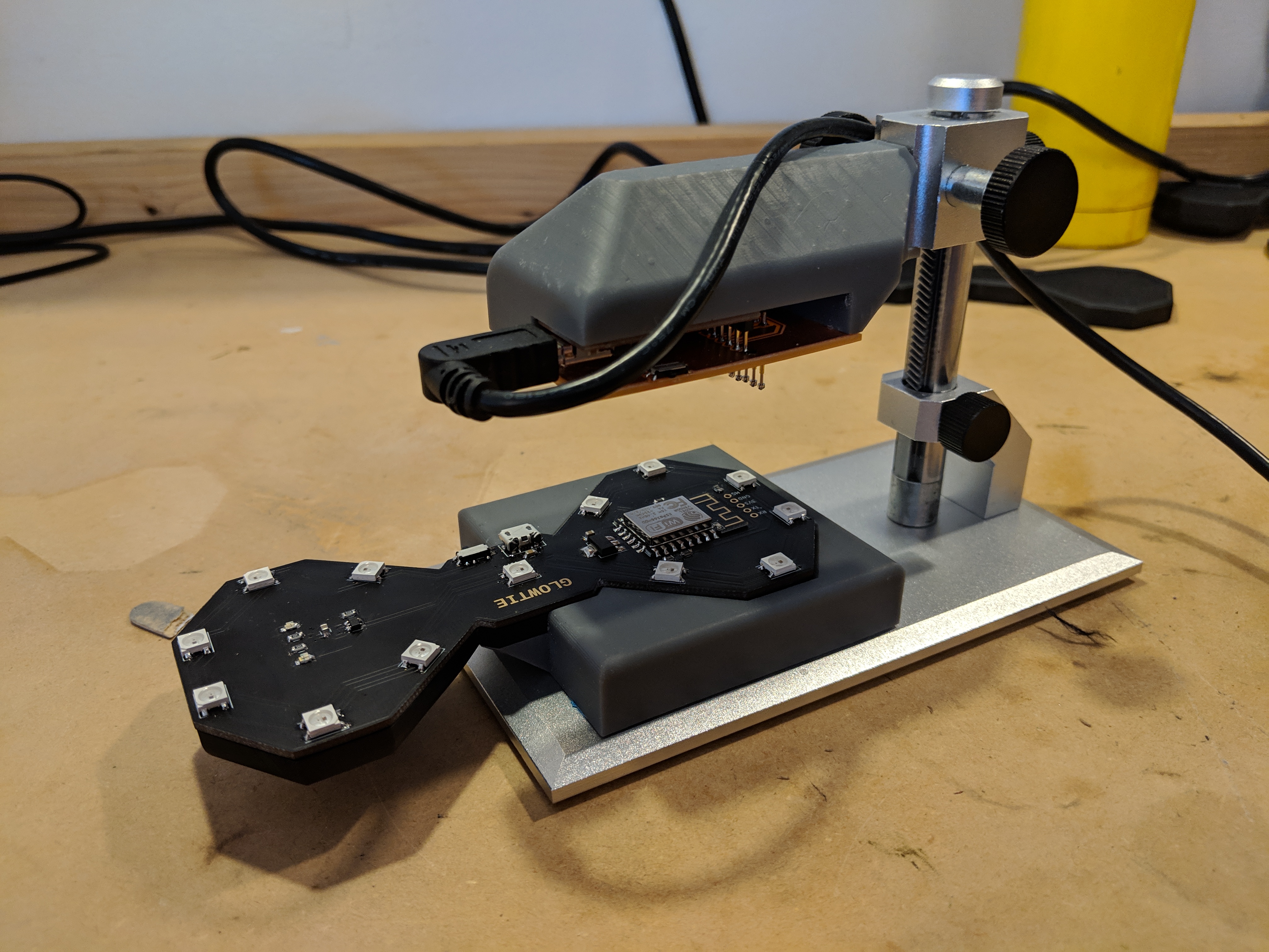
The ESP8266 module that I used, the ESP-12F, requires a few pull-up and pull-down resistors on boot to put the module into the correct mode for executing the uploaded firmware. In order to upload new firmware, one of the pins needs to be pulled to ground on boot, so I broke out the 3.3v, ground, TX, RX, and the mode select pin to pogo pin pads so I could build a programmer using a USB to Serial FTDI converter. I 3D printed a little mount that went on an old stand for a USB microscope that let me drop the programmer onto the bowtie which was held in place by a little cradle. This was much easier than holding a PCB against the bowtie and hoping I don’t lose my grip during the ~30 second programming process. It’s also great for keeping an eye on the serial monitor.
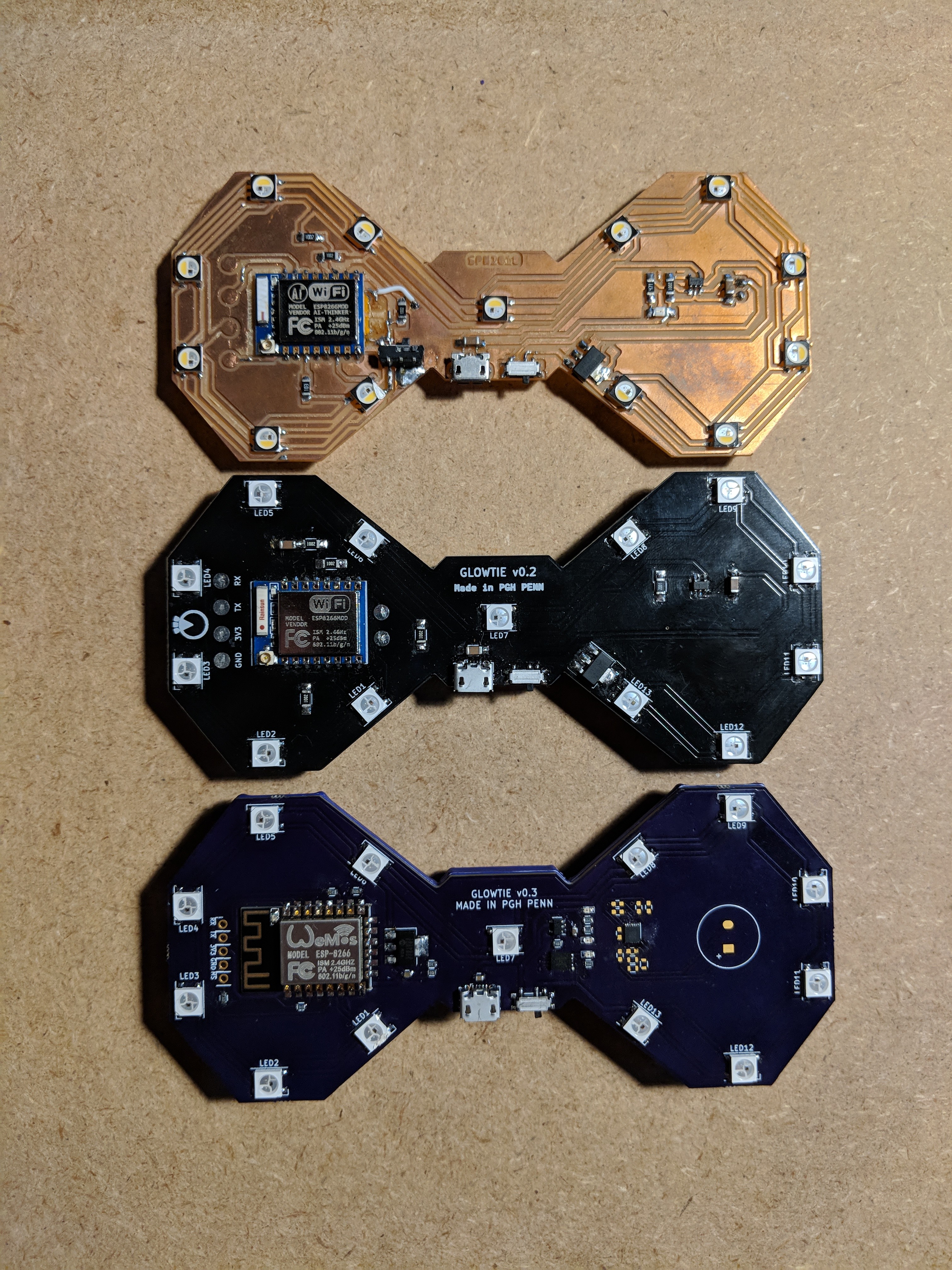
Alright, so I had a design that works, I had a rough version of firmware for testing, it’s time to order some boards! I used Elecrow for my first batch, and they came out gorgeous.

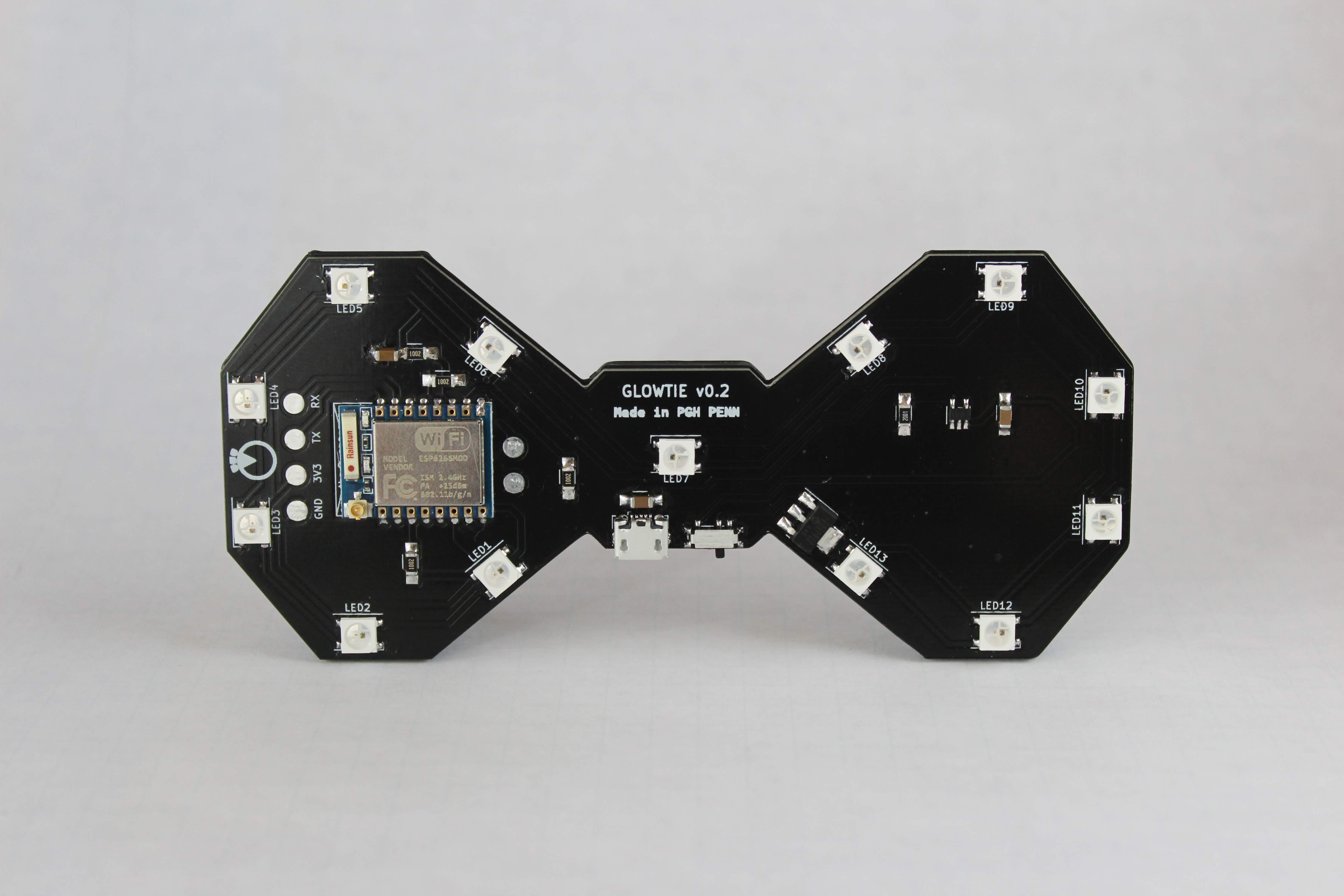
My first circuit board, designed and made from a board shop. Unbelievably satisfying putting this together for the first time. But, it had some issues.
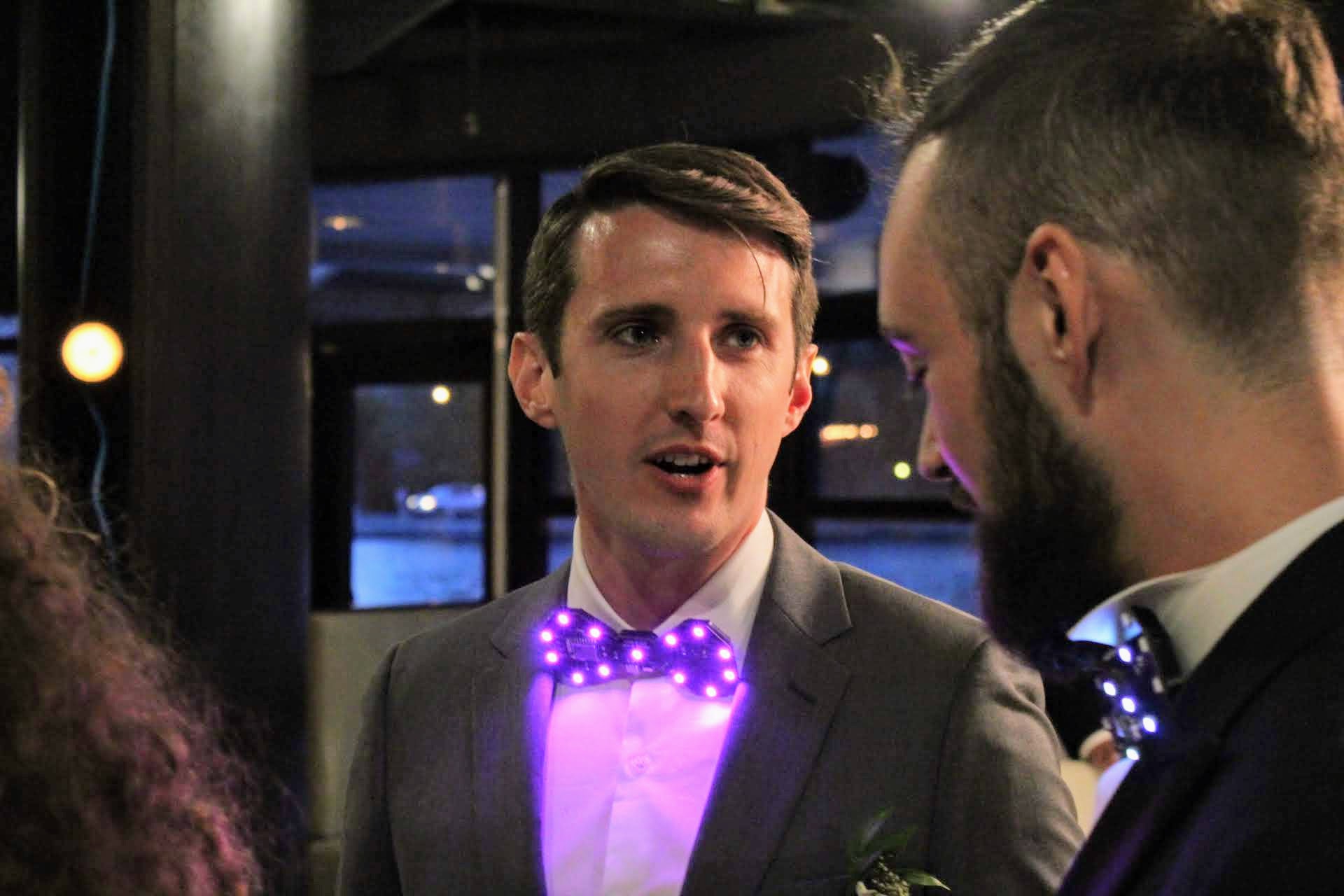
I powered the entire tie through the LDO which only had a 1000mA max current rating. The LEDs are not stingy with their current consumption, and the ESP module can pull up to a few hundred milliamps when it’s handling an HTTP request. I kept getting brown-outs and loading the webpage would continually fail. The hacky solution was to just limit the max brightness of the LEDs in software, so they weren’t consuming nearly as much power, and the LDO was able to keep up with the current requirements pretty easily, as long as the lipo voltage was healthily above the dropout voltage rating. This solve was sufficient for the wedding of a good friend of mine, who wanted some Glowties for the groomsman at her wedding!


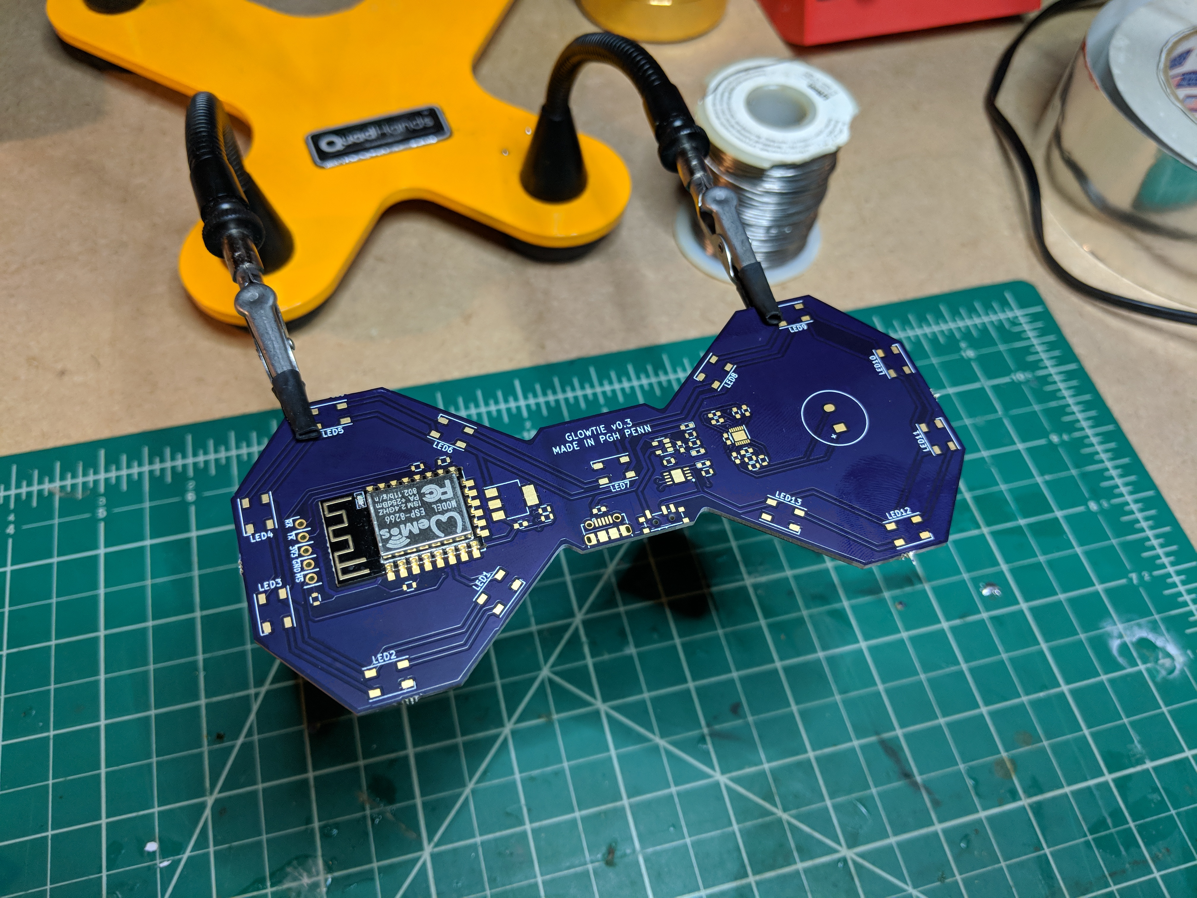
Shortly thereafter, my mom was getting married and wanted the purple Glowties for the reception. Obviously OSH Park was the solution for getting a purple circuit board. I bought some dark purple Gizmo Dorks ABS for the back piece, and took advantage of ordering a new set of boards to fix my power consumption issue. This time, I just put the ESP behind the LDO and just ran the LEDs straight off of battery power. This is also beneficial because now the Neopixels are actually getting a supply voltage within the range specified on their datasheet. I originally didn’t want to power the LEDs directly from the battery because I was worried that the brightness would vary as the battery depleted, but I’ve found no change in brightness within the 3.5v-4.2v range of the lipos.
I also took the opportunity to test out a I2C lipo battery monitor chip to keep an eye on remaining power, and left the single ADC to connect to a small microphone circuit with an auto-gain adjusting amplifier, allowing the tie to react to sound. Still working on the firmware to integrate that feature, so for now it’s left unpopulated. Future versions might have this included!
 Me, my stepdad, and my brother at my mom’s wedding wearing Glowties
From here, it was just minor tweaks until I had a finished design ready for the Kickstarter!
Kickstarter
On Wednesday February 20th, 2019 I launched the Kickstarter for the Glowtie. It was funded in two days, and at 234% of the goal!
Sourcing
Getting parts sourced for this project was a little weird. The quantity that I needed to make was right at that weird scale where I’m not quite hitting a lot of Minimum Order Quantities (MOQs) from most vendors. I was generally confined to vendors that had an MOQ of 100 or less, or I had to buy parts from a distributor at a huge markup. Each Glowtie required 13 LEDs, so that meant I was able to hit a 1000 MOQ for them, but in general it was a struggle.
As a result, I only sourced a few parts for the project from a proper vendor via Alibaba: the braided USB charging cable, LEDs, and microcontrollers.
Assembly
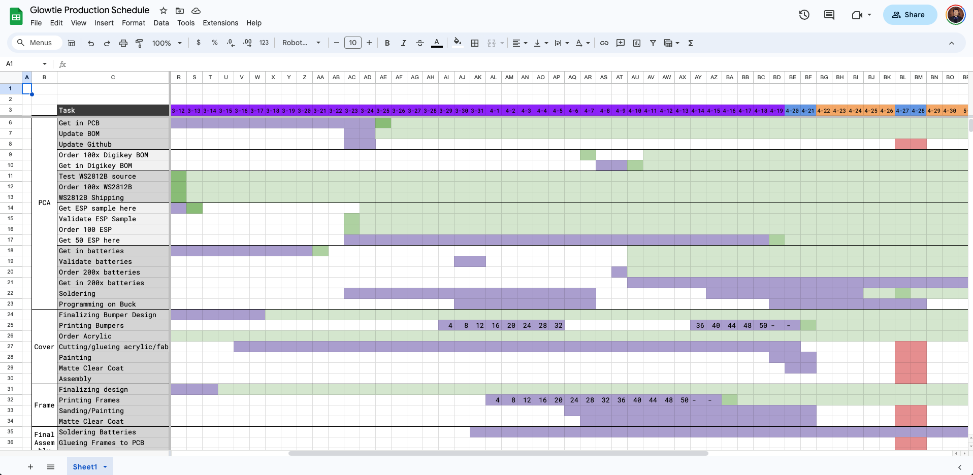
I was adamant about hitting my shipping deadline. I didn’t want to have a single thing go out late, so I made a Gantt chart in Google Sheets to track when each task needed to be done in order to prevent a delay from cascading into all of the other dependent tasks.
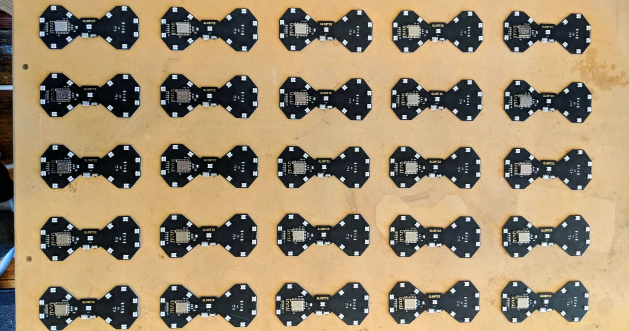
Now I actually had to make all of them! The first step was making all of the PCBs. I spent my spare time for months hand-populating dozens of circuit boards, and reflowing them in my Mom’s old toaster oven.
I also 3D printed all of the frames on my Form 2 at work, which ended up being quite a bit of work. Every print needed to be washed in IPA, cured with a second pass of UV exposure, supports removed, touchpoints sanded, rinsed, then two coats of paint and a protective clearcoat.
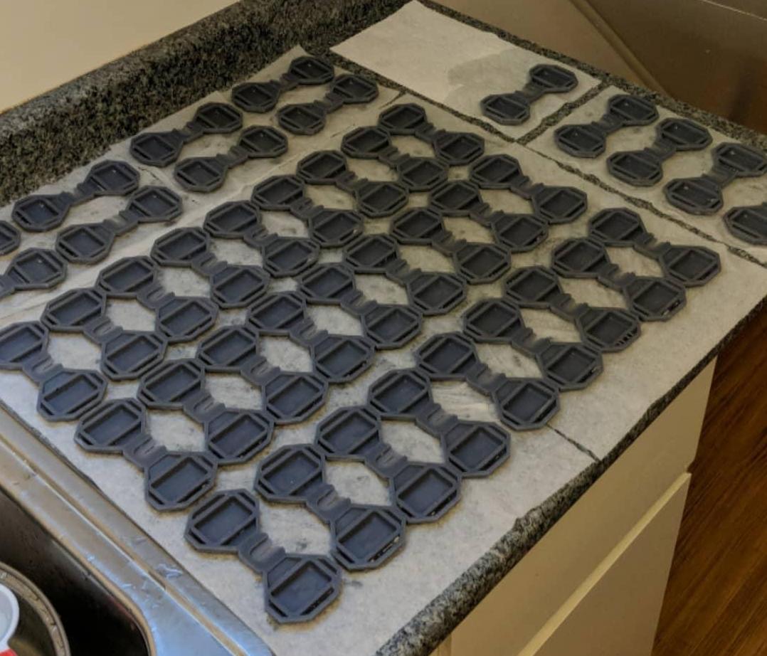 Letting all the prints dry after a rinse on my kitchen counter
Then it was gluing the frames onto the PCB, and putting production firmware onto them.
However, I was only half done. I still had to fabricate the covers.
The covers are really what brought the Glowtie from a goofy gizmo for a circuit board nerd, to something anyone might wear to an event. Covering up the PCB, and adding a bit of class and nuance to the light-up effect was definitely the clincher.
But they were miserable to make.
Through experimentation I realized that the only way to get a nice even diffusion of the light was to use 1/8” acrylic that had been sanded down with a medium grit sandpaper. I did this for only about five Glowties before I started searching for another option.
I decided to try raster etching the diffusion on a laser cutter! I already had the acrylic loaded into the machine to cut the profiles, so just adding an extra operation to raster engrave and add the diffusion automatically would save me a ton of time and sanity.
It ended up working out great. I had to babysit the laser cutter for a couple hours (!) but I was able to work on something else while it was gleefully etching along.
Once they were etched, I gave them all a rinse and adhered them to the covering fabric. I actually brought a glowtie with the diffusion to a fabric store and tried a few dozen black fabrics until I found one that allowed the light to shine through well.
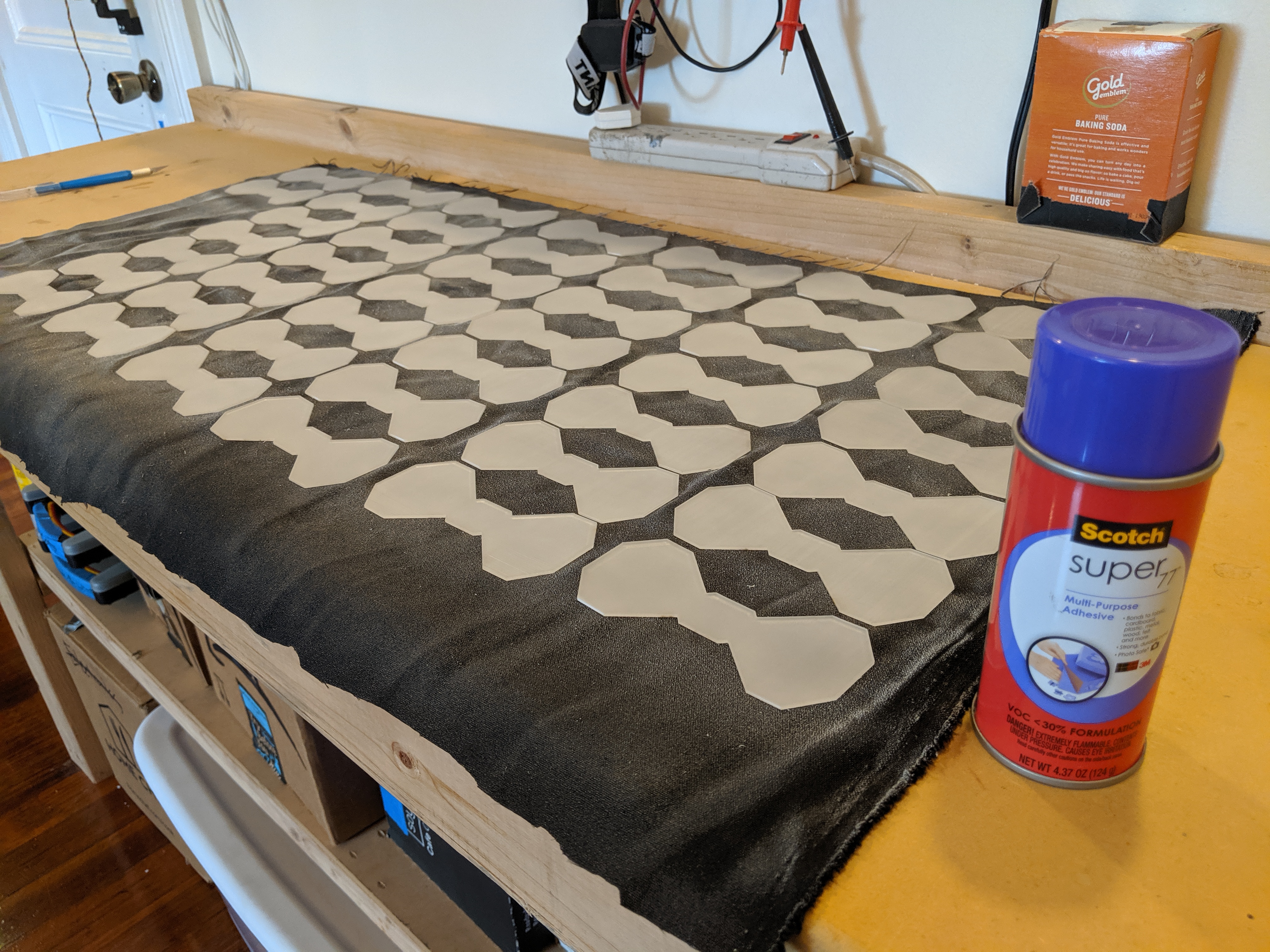 Using some Super77 spray adhesive to attach the fabric to the diffusion
Then it was gluing the fabric/diffusion combo into the frame print, attaching them to a frame, packing them up, and shipping them out!
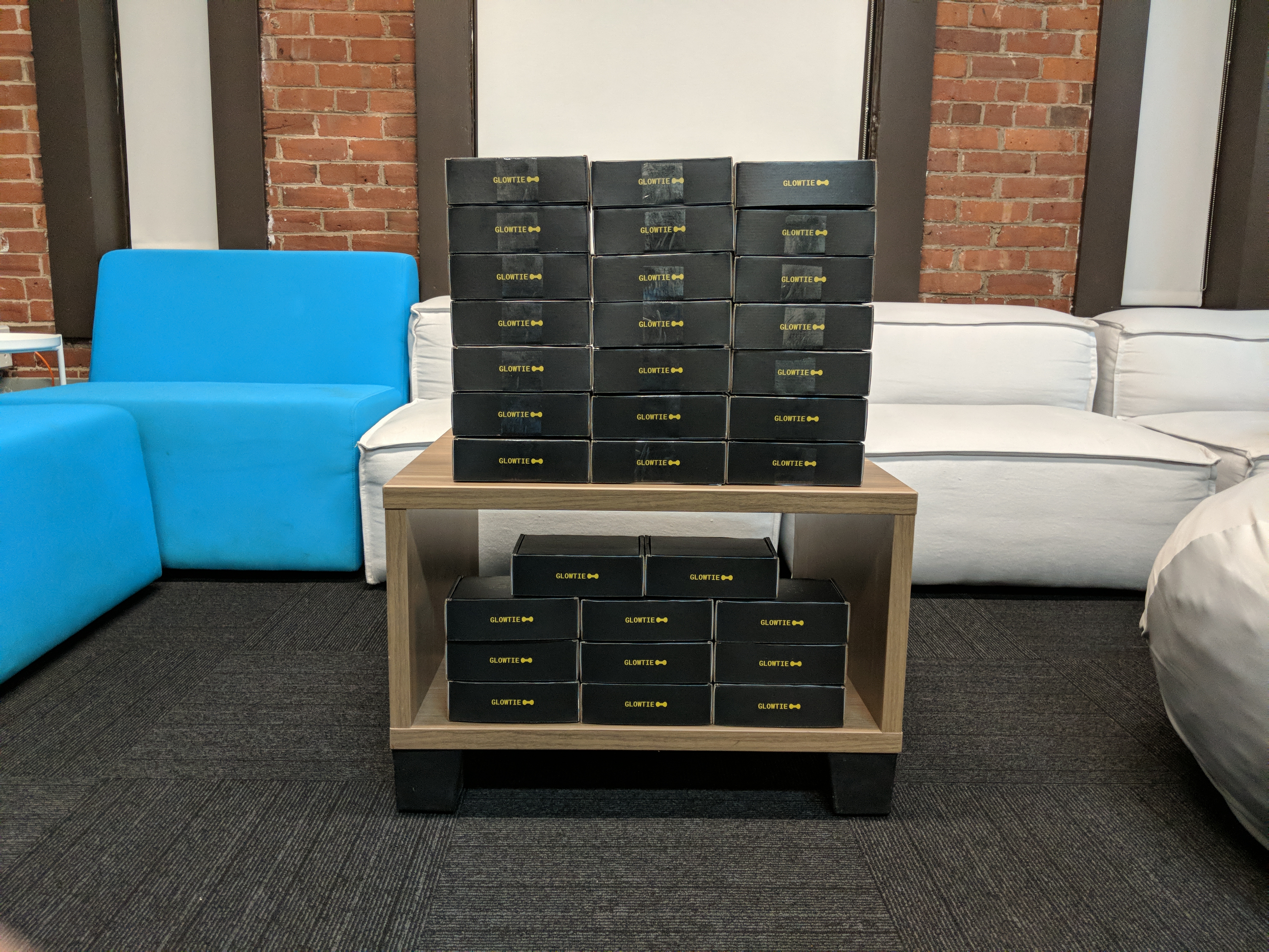
The relief I felt getting these boxed up is hard to describe. It consumed my nights and weekends for six months.
Takeaways
I took pretty detailed records of all expenses related to the project. In total, it cost me $1768.07 including packaging, PCBs, compoenents, shipping, stickers, foam, batteries; everything I needed to spend money on to get these units out the door. The Kickstarter raised $4,694, minus a 5% cut to Kickstarter (and some miscellaneous fees) resulted in a profit of ~$2775.
Not too bad! Turning a profit on a small run hardware project was definitely unexpected. I was fully prepared to take a loss on this. So why did it pan out this way?
First and most important, I didn’t hire a company or an employee to help assemble them. Not included in the costs was my labor, which was “free.” If I had someone helping me put these together, I probably wouldn’t have turned a profit. All of the required engineering work was free as well.
Second, I had already purchased or had access to many of the tools needed to complete fulfillment. My Taz 5 at home and Form 2 at work allowed me to print all the necessary parts, and incurred no capital expenditure. I was also able to use Formlabs’ laser cutter for raster etching and cutting the acrylic, and cutting out the packaging.
Lastly, this device is small. The components weren’t expensive, the testing was simple, and it’s very inexpensive to ship. A large desktop-sized machine introduces a plethora of other complications that decimate any profit from a small run.
If you actually break down the time I spent putting all of the production units together, greater than 60% was just assembling the circuit boards. Each PCB only had a few dozen components but hand-placing them consumed hours of my time that could have been spent doing something else. This feels like the most neglected step of small batch assembly in terms of optimization and tools.
I looked into purchasing a pick and place machine to help me with assembly, but didn’t find much in my price range that would be more of a help than a hinderance.
This project was a fantastic exercise in what it means to ship a hundred of something, and all the little details and gotchas that come along with it.