3D Scanner
During my sophomore year of college, I developed a 3D scanning machine with my friend Lucy by request of a company in Stamford, Connecticut. We were asked to design and fabricate a machine that could take a 3D scan of one or two people, full size.
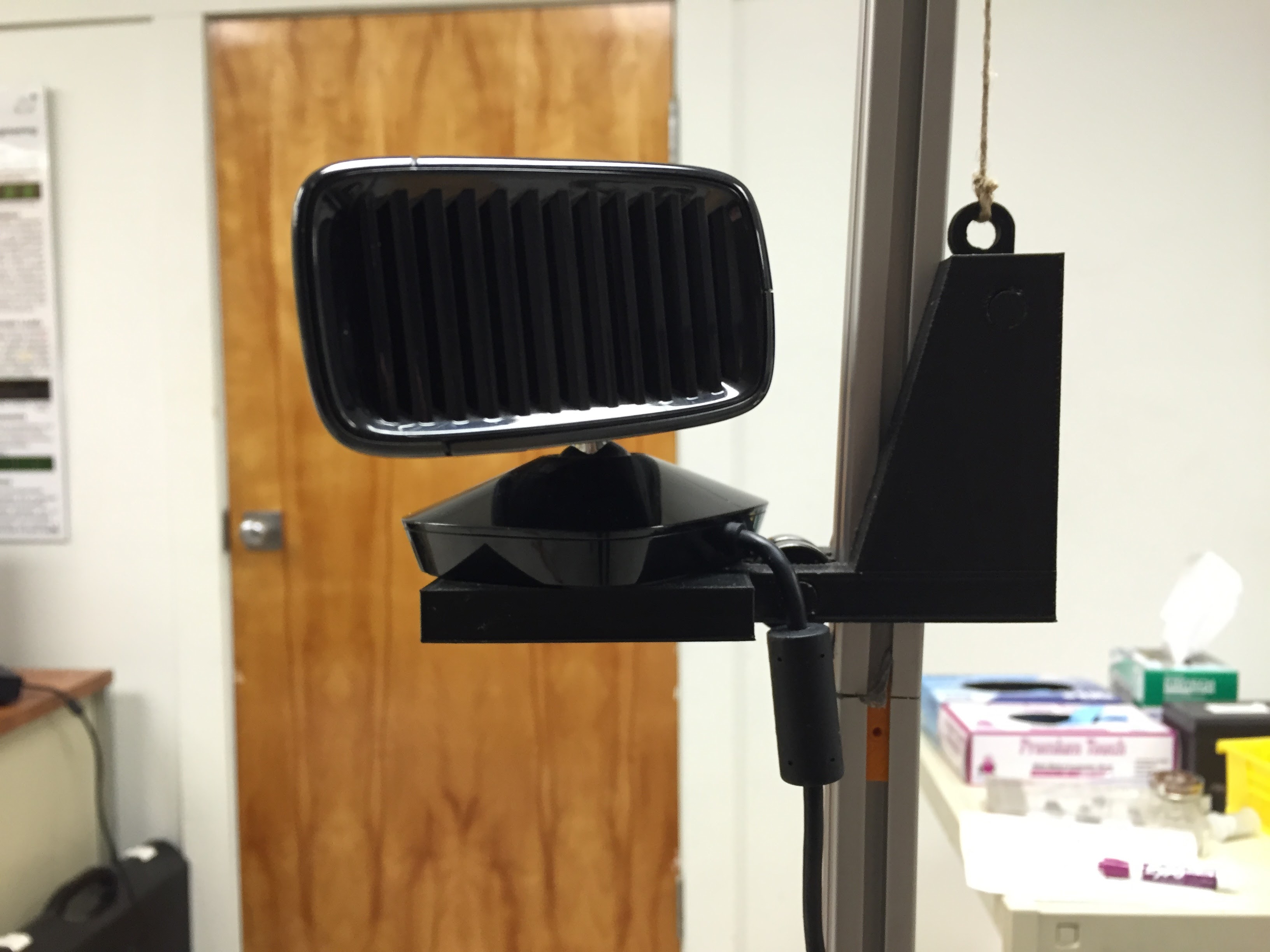
We decided to use an Xbox Kinect, as there is already a substantial amount of software available that can render a 3D mesh using this hardware. After some initial tests, we decided on a pedestal that rotates the object being scanned, and the Kinect on a vertical axis that moves up and down in order to capture the object’s entire geometry.
Carriage
First up was designing the carriage to carry the Kinect. It had to be able to slide along a 20mm x 20mm aluminum extrusion with little to no friction, but also be sturdy enough to not botch a scan due to tracking loss. After going through a few design iterations, I settled on a design.
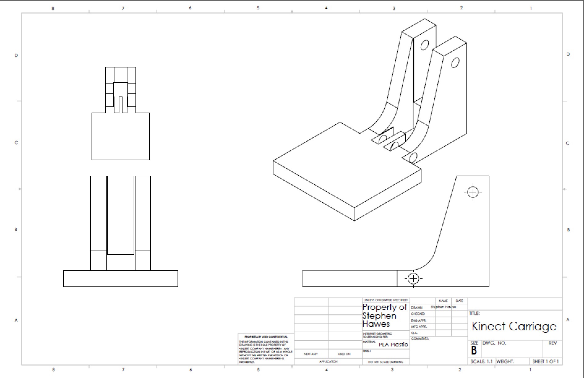
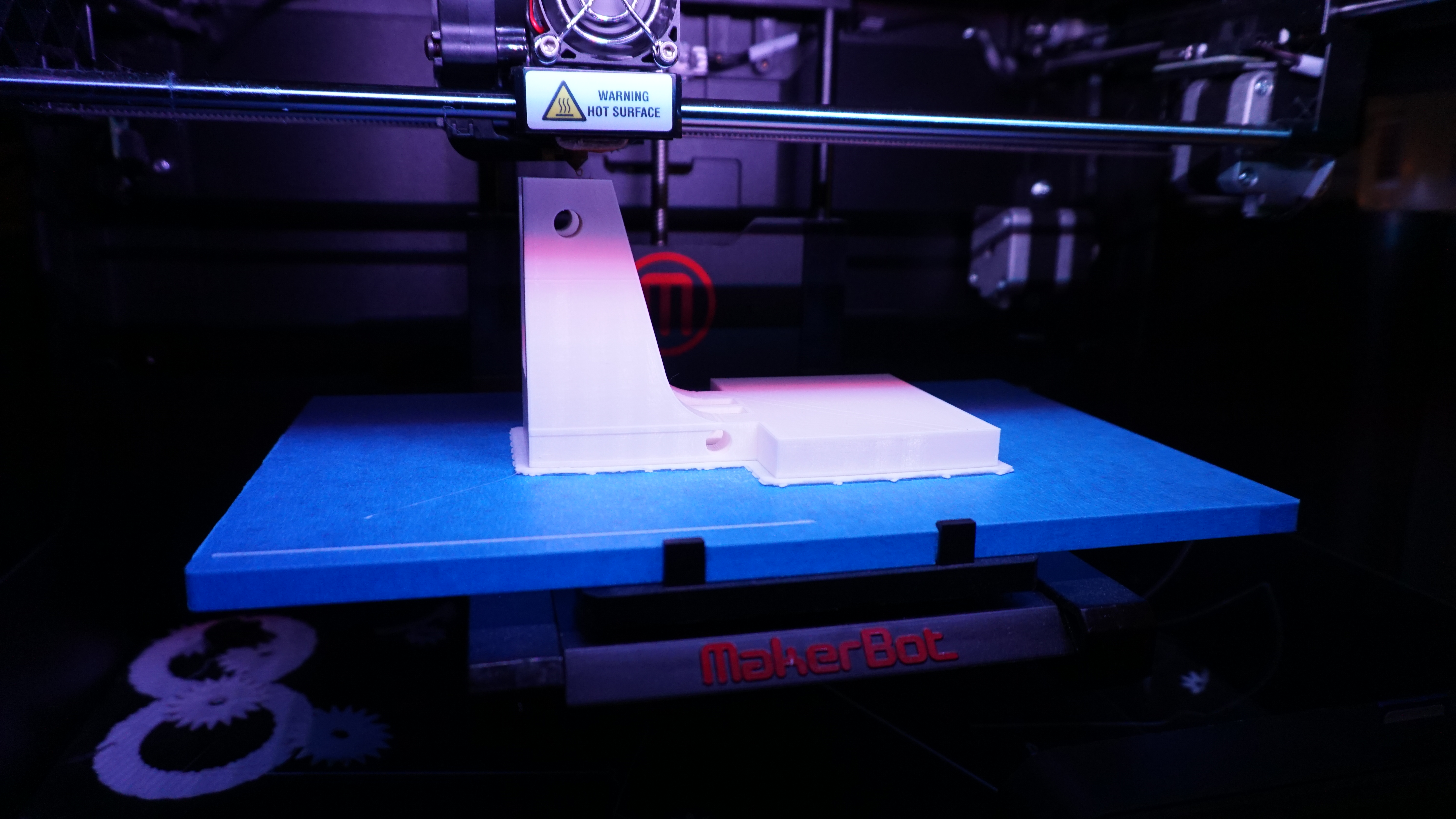
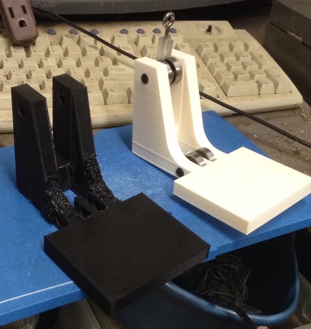
This part uses the weight of the Kinect to help stabilize the gantry. The force of the Kinect downwards causes the two sets of bearings to push forcefully on the aluminum. We printed one out in some spare filament on my Solidoodle 2 Pro.
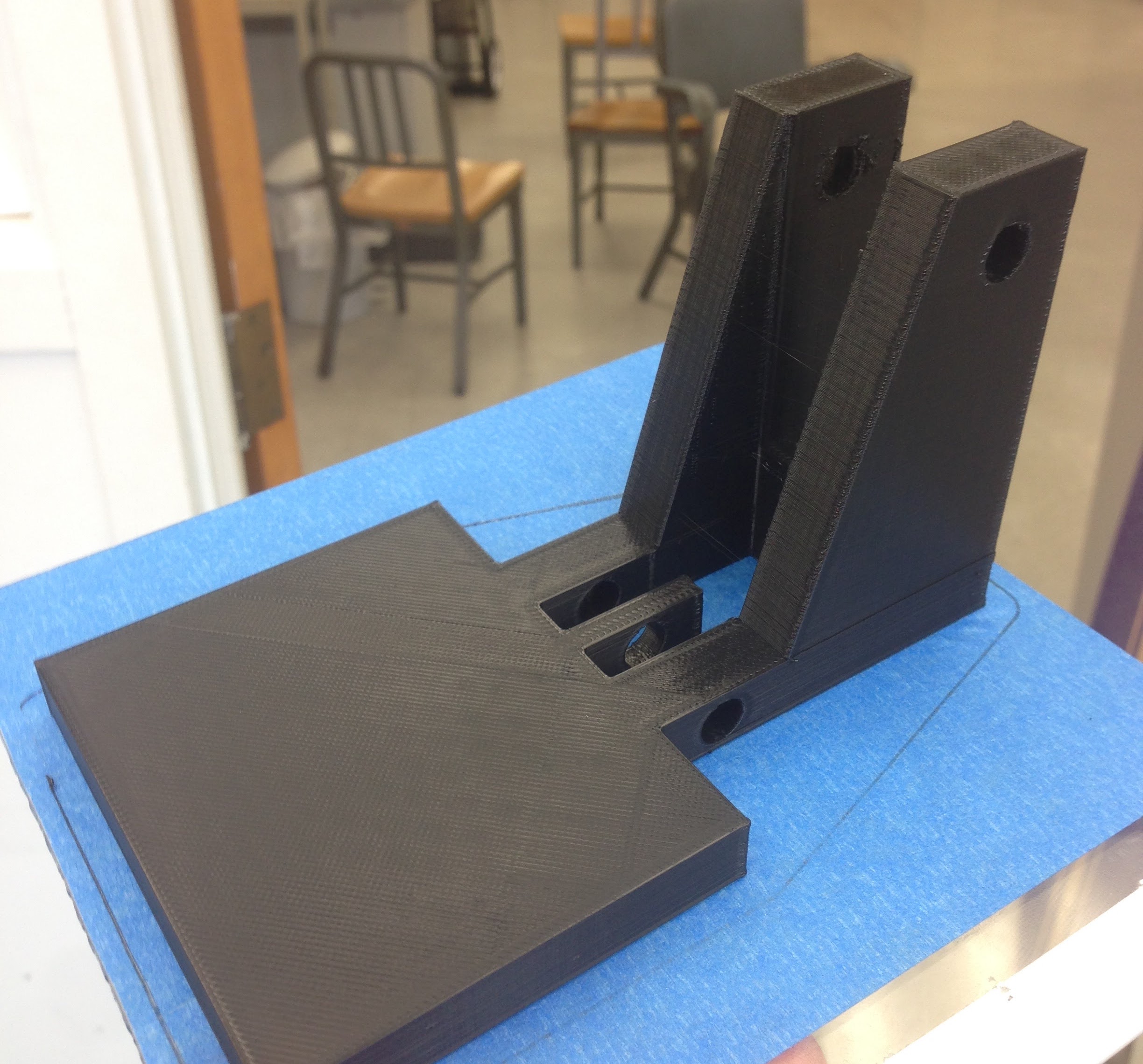
But it very quickly broke after only a couple tests.
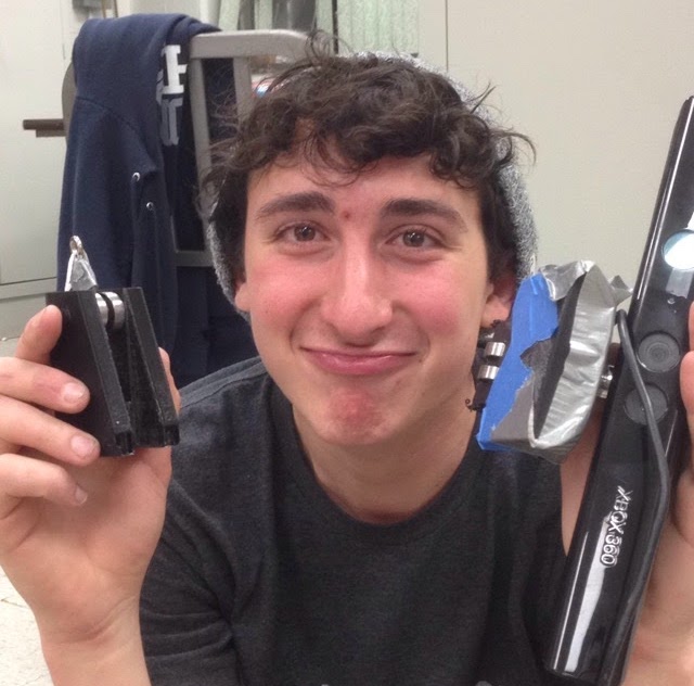
This was due to insufficient print settings, and crappy filament. We upped our infill and shell count, and got some high quality filament and printed a replacement.
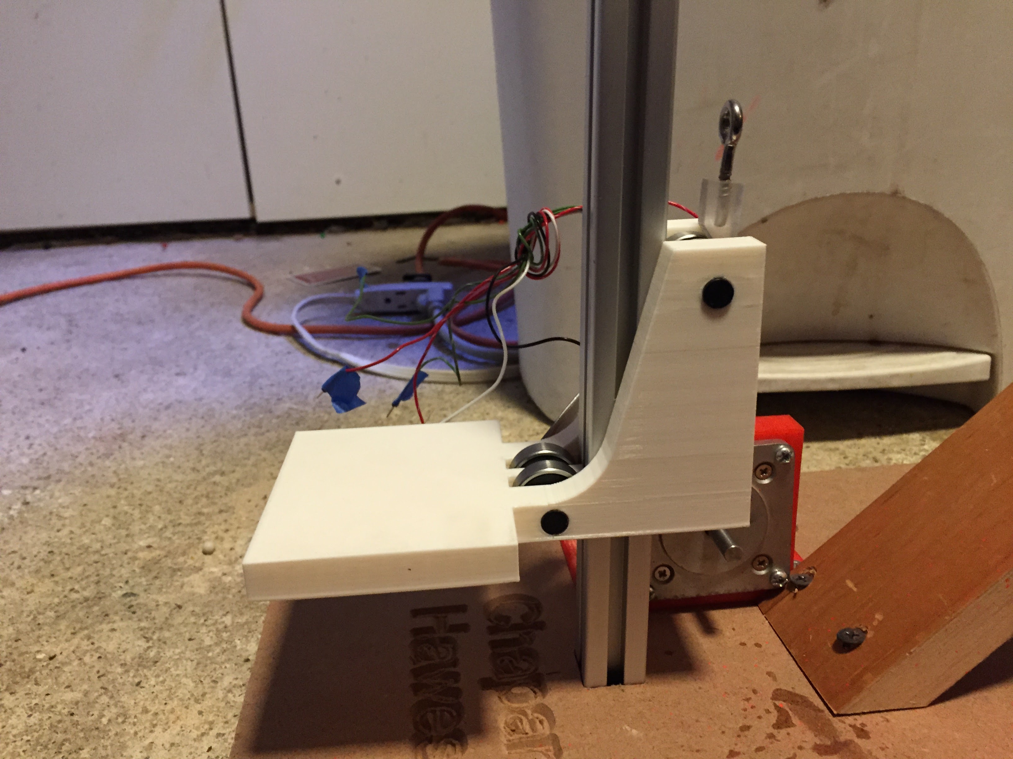
Also, it is worth noting that the Kinect carriage is moved using a pulley system. Using a “gun tackle” design, we get a 2:1 mechanical advantage, meaning the force required to lift the Kinect is only half its weight, at the cost of winding twice as much wire. I included this feature so that the stepper motor would only have to lift half as much, and have a lower likelihood of skipping steps.
The carriage was driven by a stepper motor with a limit switch for accurate positioning.
Electronics
The scanner needed a handful of electronic modules to control the motors and communicate with the desktop application. The controller board for the scanner is comprised of an Arduino Duemilanove, a Pololu A4988 Stepper Motor Driver, a small 5 volt relay board, and a 12 volt DC motor controller. The stepper driver controls a stepper motor that moves the Kinect carriage, and the DC motor controller runs a 12 volt motor that rotates the pedestal. We also needed a limit switch so the stepper can find the carriage’s position.
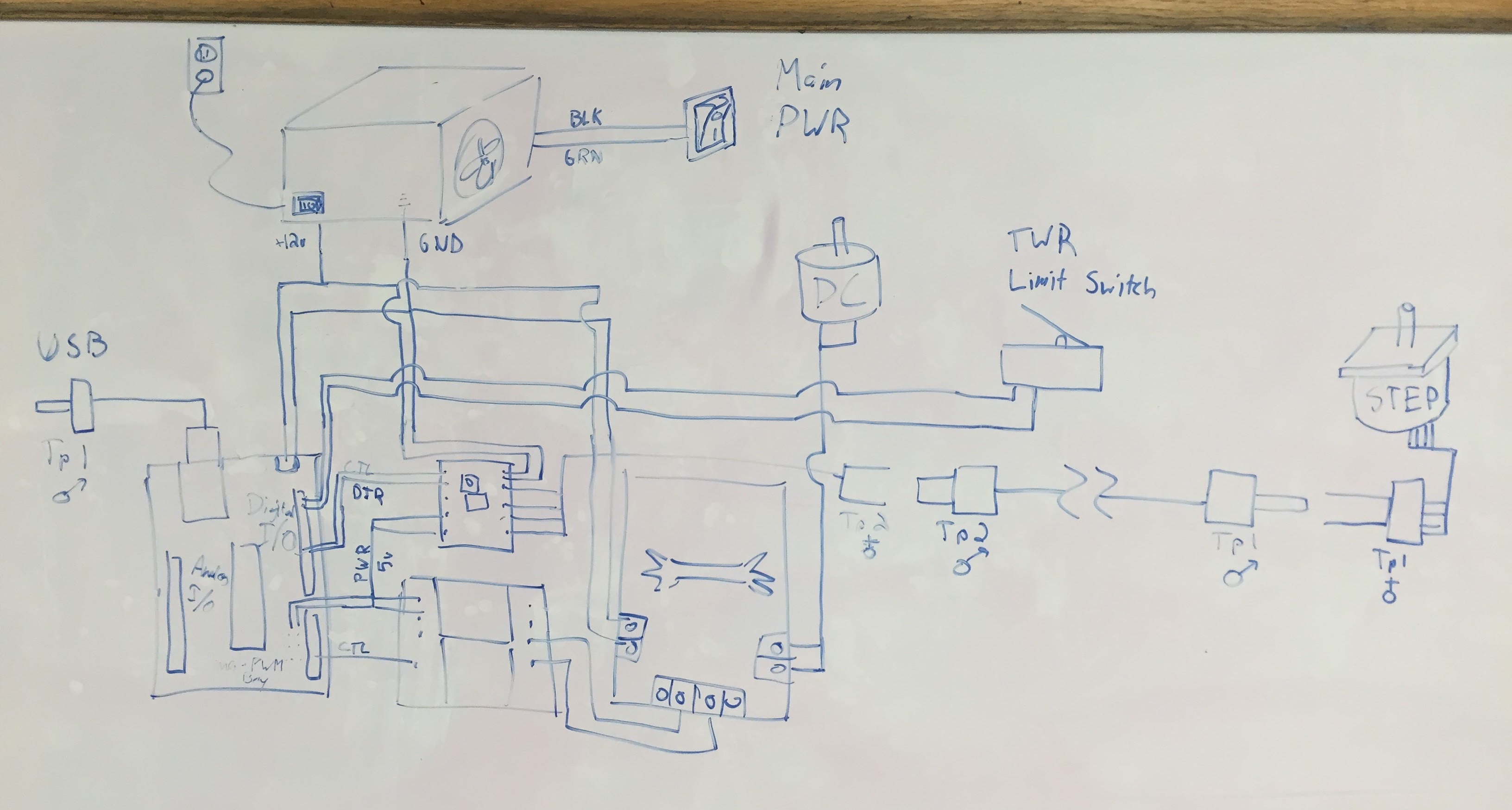 System diagram for the machine
At the core of this is the Arduino, which just needs to receive commands over USB from the desktop application and control the motors accordingly.
I set up shop in the lab of the gracious Adam Wentworth and started building out the control panel.
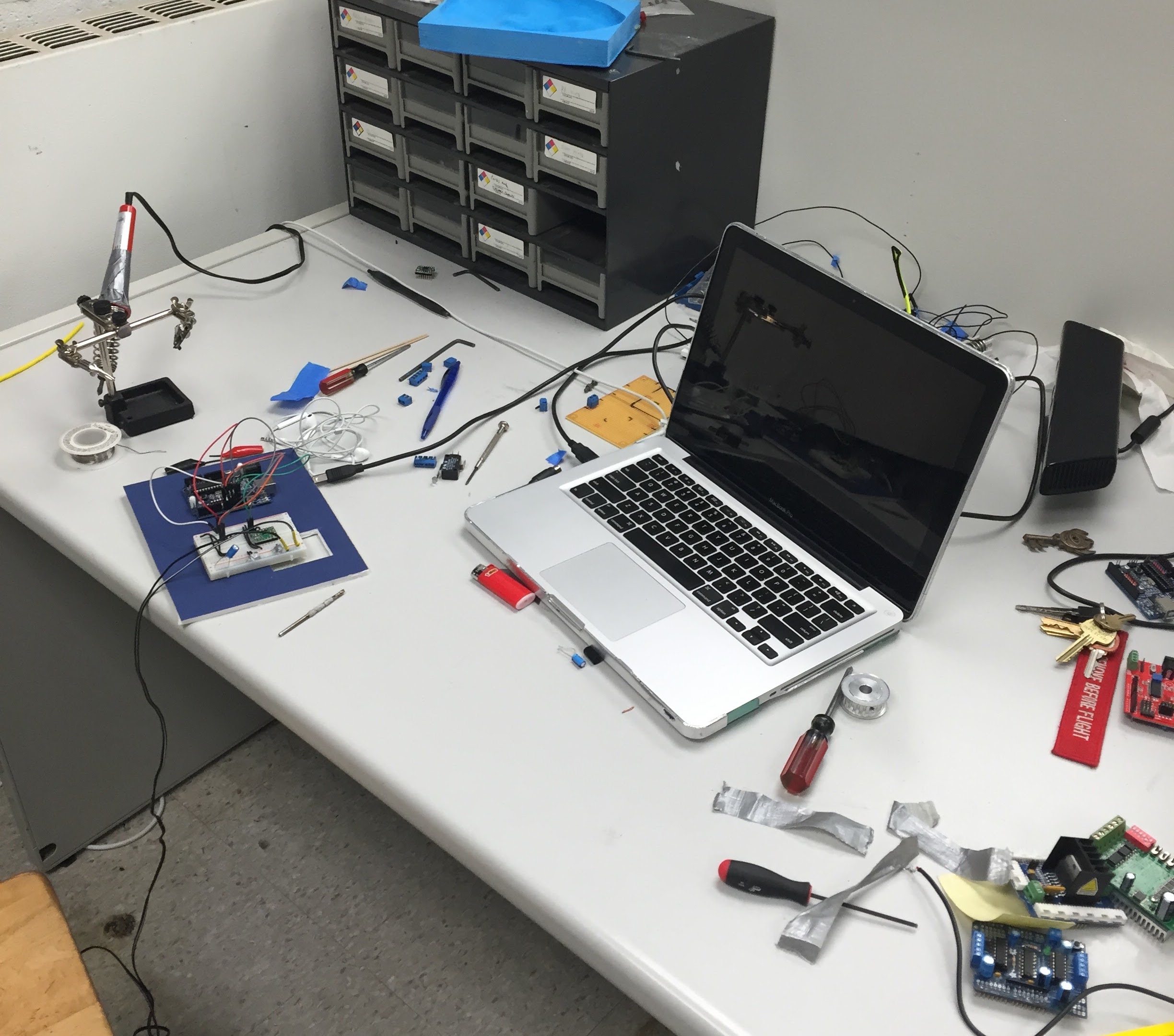 Temporary workspace
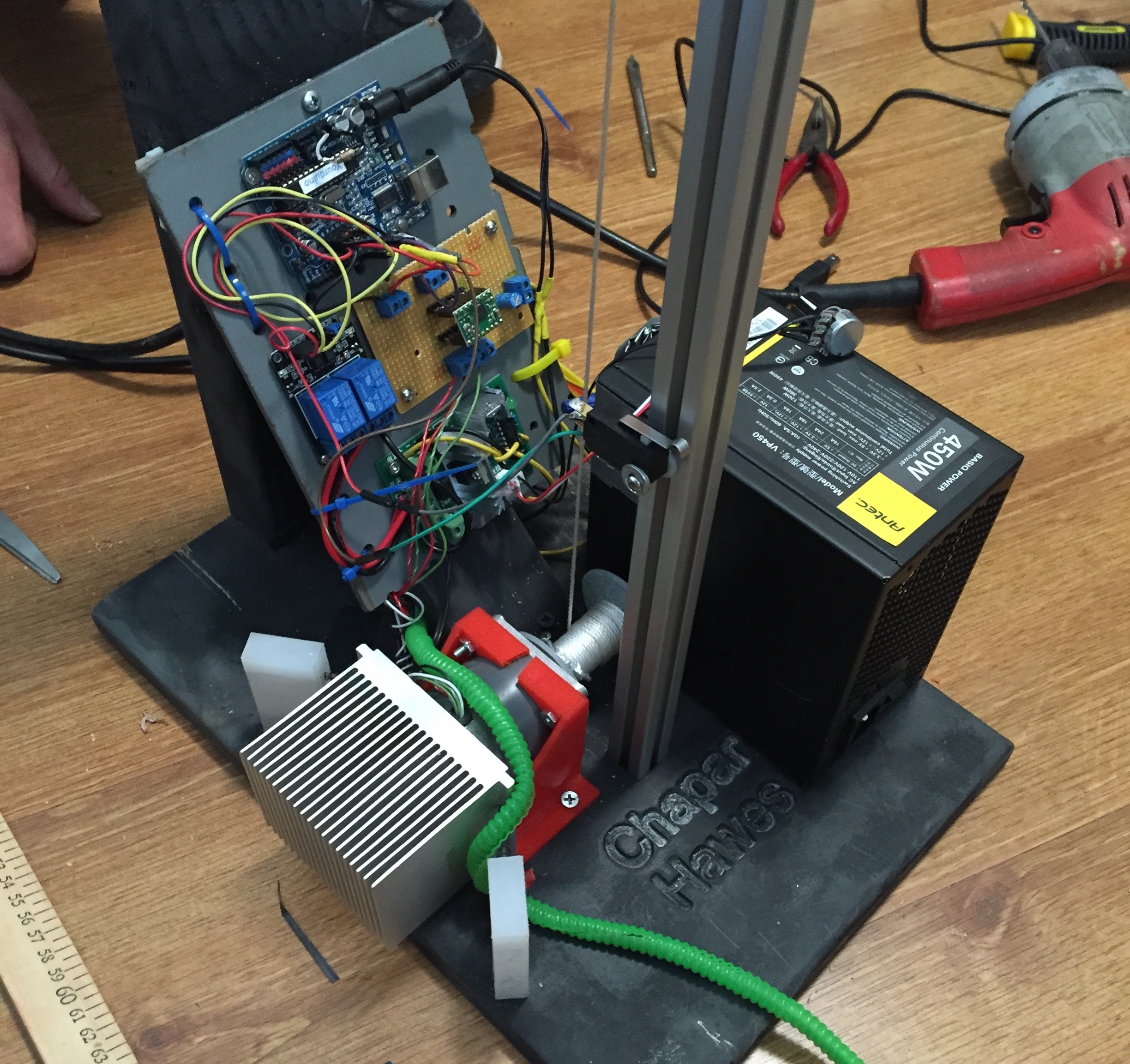
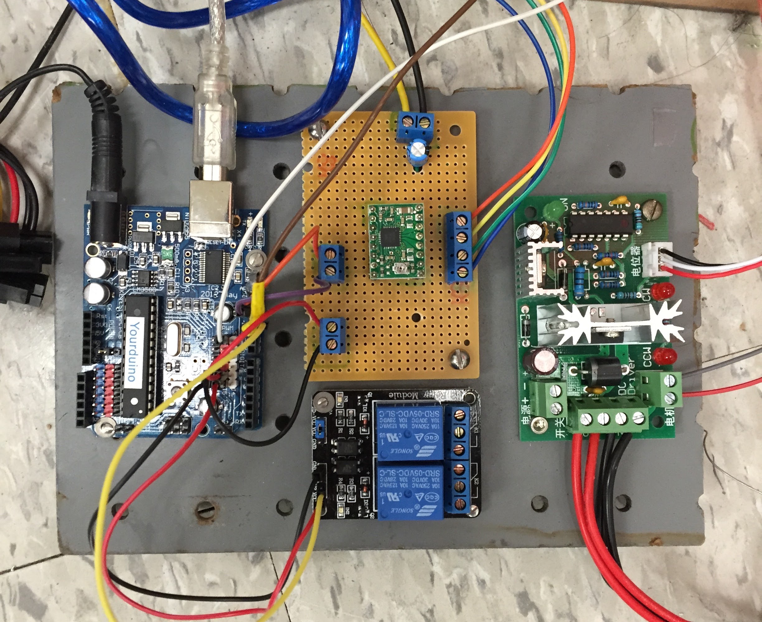 Main components bolted up
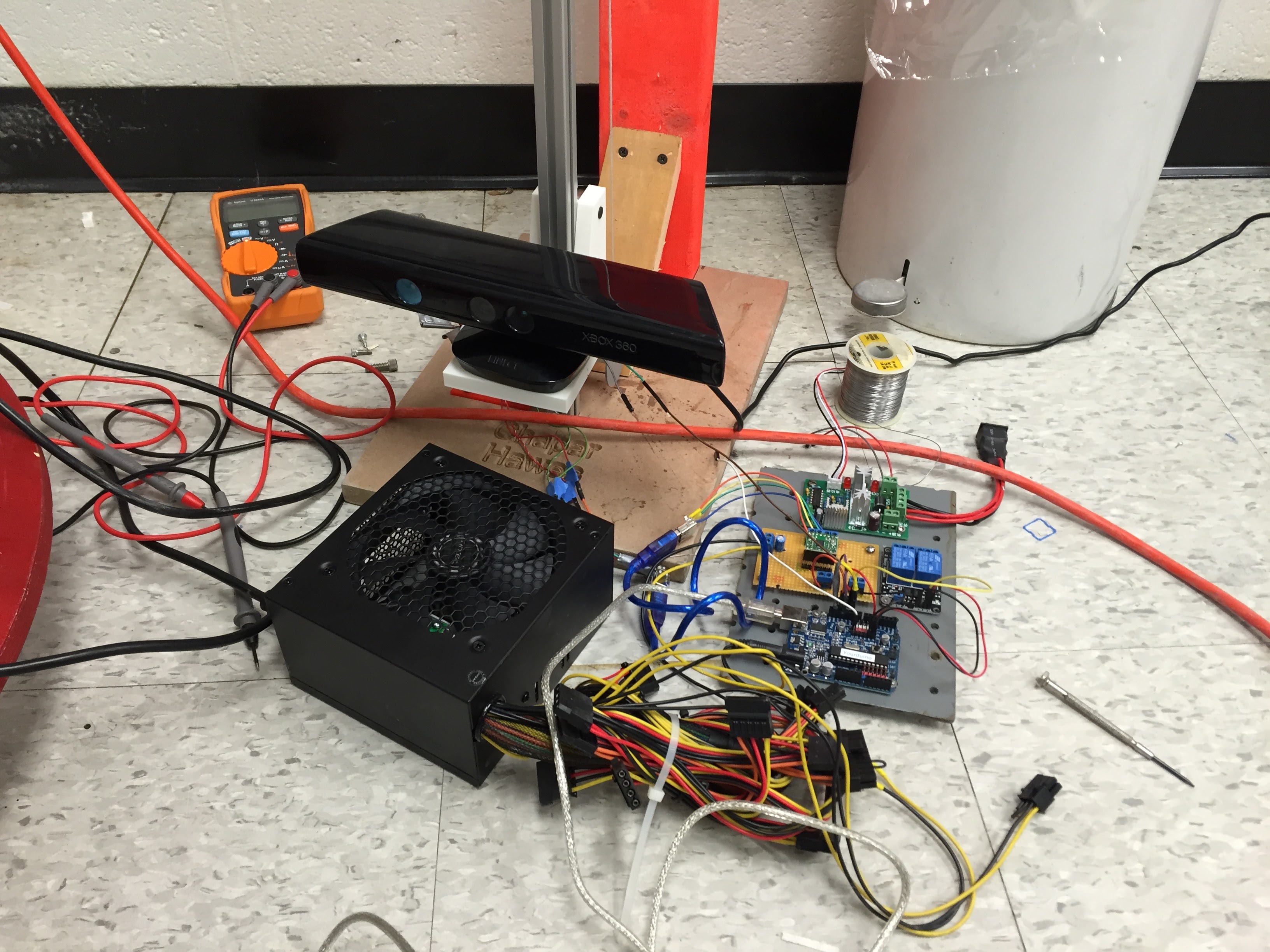 Connected to the tower
Software
With most of the machine built, I set to work designing an app in Java to control the scanner. I designed a basic UI with functionality to run a scan sequence based on user-defined settings, connect and disconnect from the scanner, and to jog the tower up and down ten centimeters.
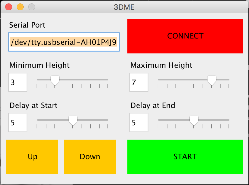 The final UI of the desktop application
Then I wrote some firmware for the Arduino to run the motors based on the settings from the app. I wrote an algorithm that takes the minimum and maximum height to be scanned, calculates how many different pedestal rotations are necessary, and how high up the Kinect needs to be for each one. Then it will move the Kinect carriage to that first position, stop, rotate the pedestal around once. Then the process is repeated until the entire object is scanned.
While this process is happening, Scanect is running a capture to actually take in the data from the Kinect and form the mesh.
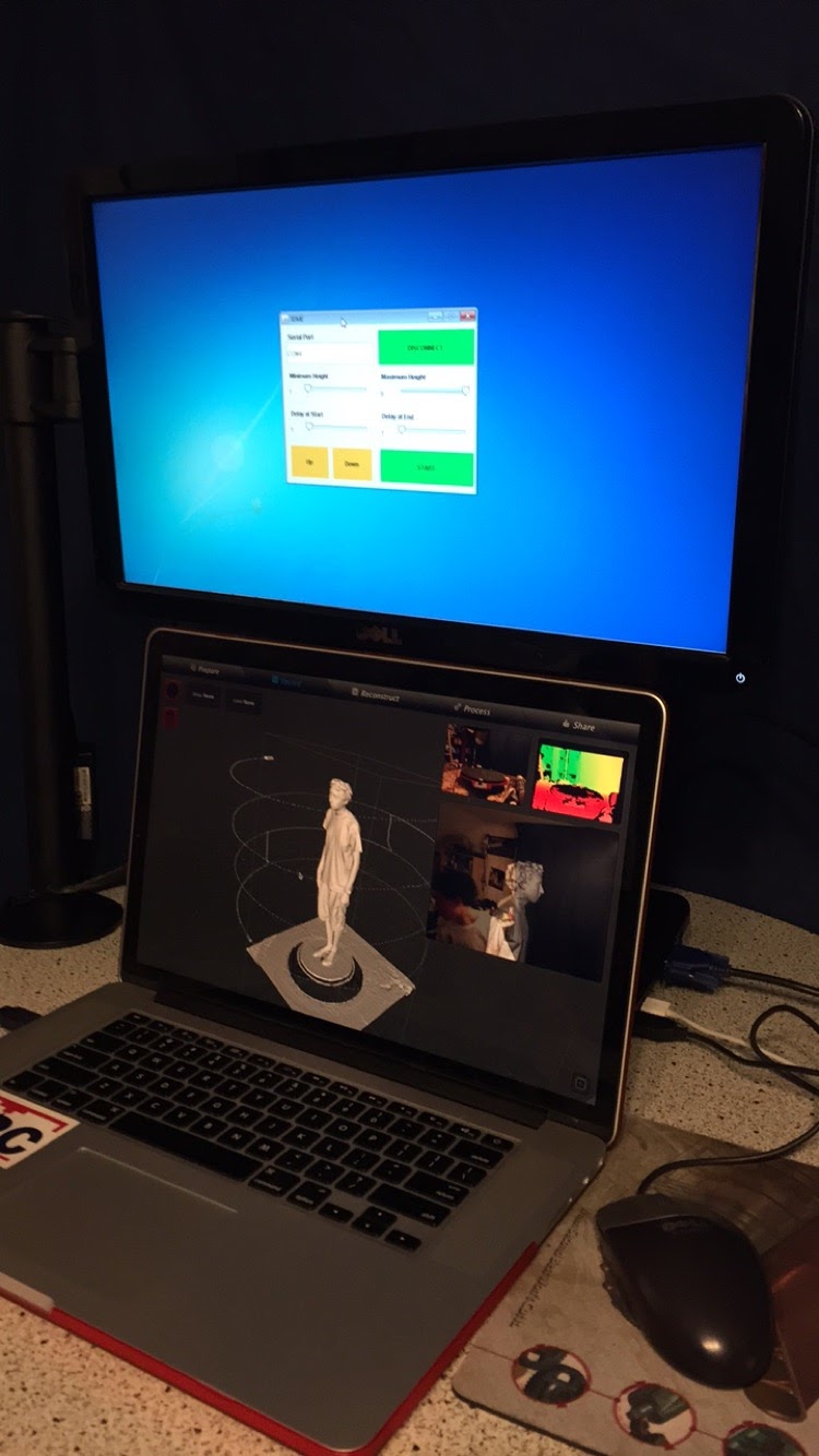 Both applications ready to run a scan
Getting the machine to perform movements based on a defined set of parameters was one of my favorite parts of this project. Writing instructions and having a machine operate based on them is a deeply satisfying experience.
 Testing the tower homing sequence
Pedestal
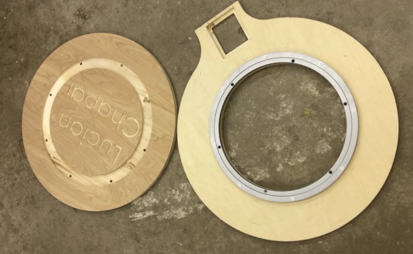
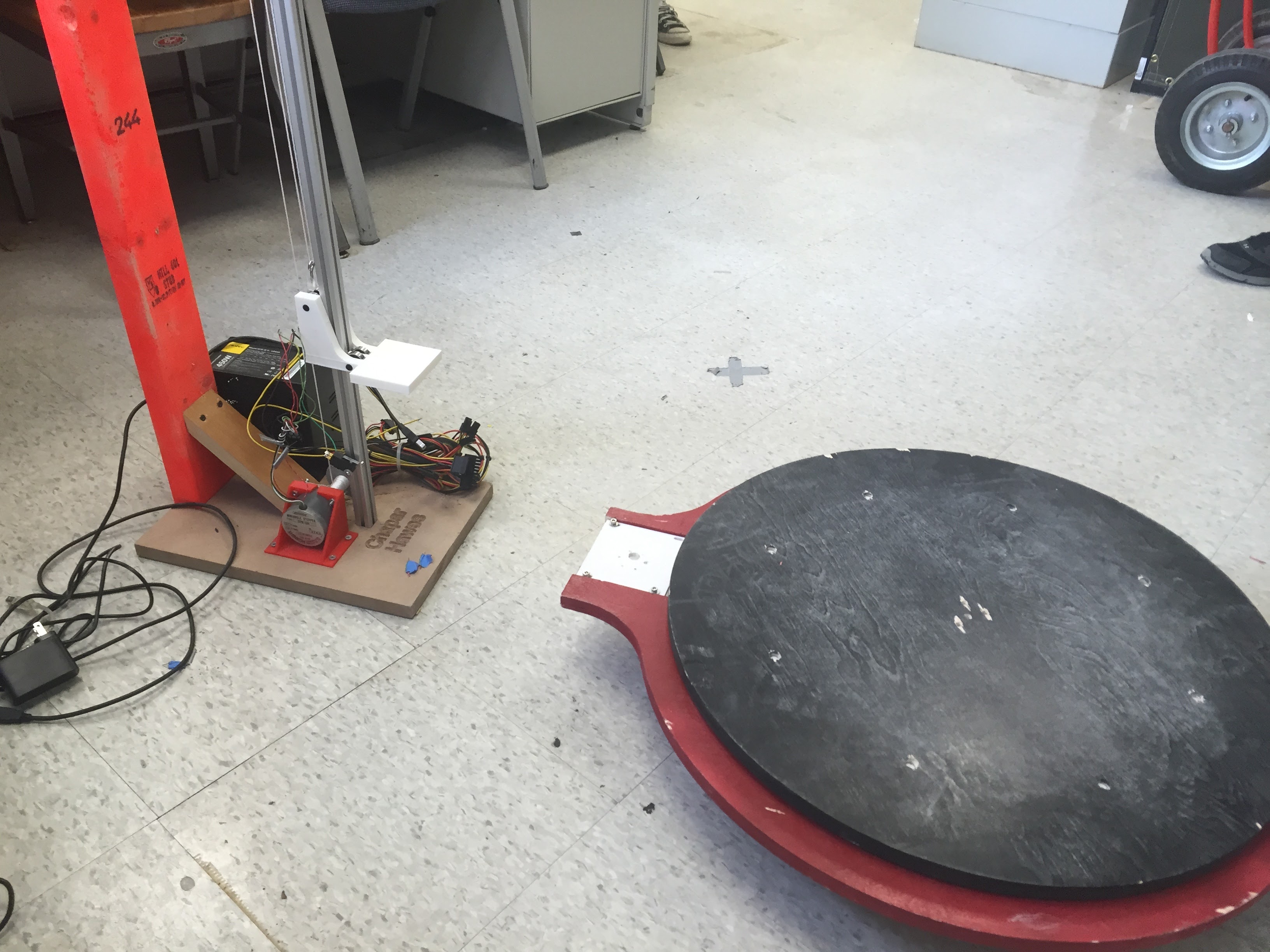
While I was working on the software and electronics, Lucy was focusing on the pedestal. It needed to be able to rotate up to 500lbs [227kg], be incredibly sturdy, and be able to tell the base unit when it was at a “home” position.
Lucy milled out the base on the Shapeoko in the UConn Art department’s shop, and attached a humongous lazy susan bearing.
Because we didn’t really care about the exact position of the pedestal, we were able to use a more powerful DC motor for rotation.
Lucy and I were on a tight college kid budget, so we tried to find ways to save money on the build wherever possible. The best example of this is the sprockets we used to transfer power from the motor to the pedestal itself.
McMaster-Carr has a wonderful website full of engineering drawings and 3D models of most of their products. While Lucy and I were looking for sprockets, we realized that we could download a 3D model of the ones we were thinking about buying and 3D print them to test. The printed ones ended up being plenty strong for our application, so that’s what we used!
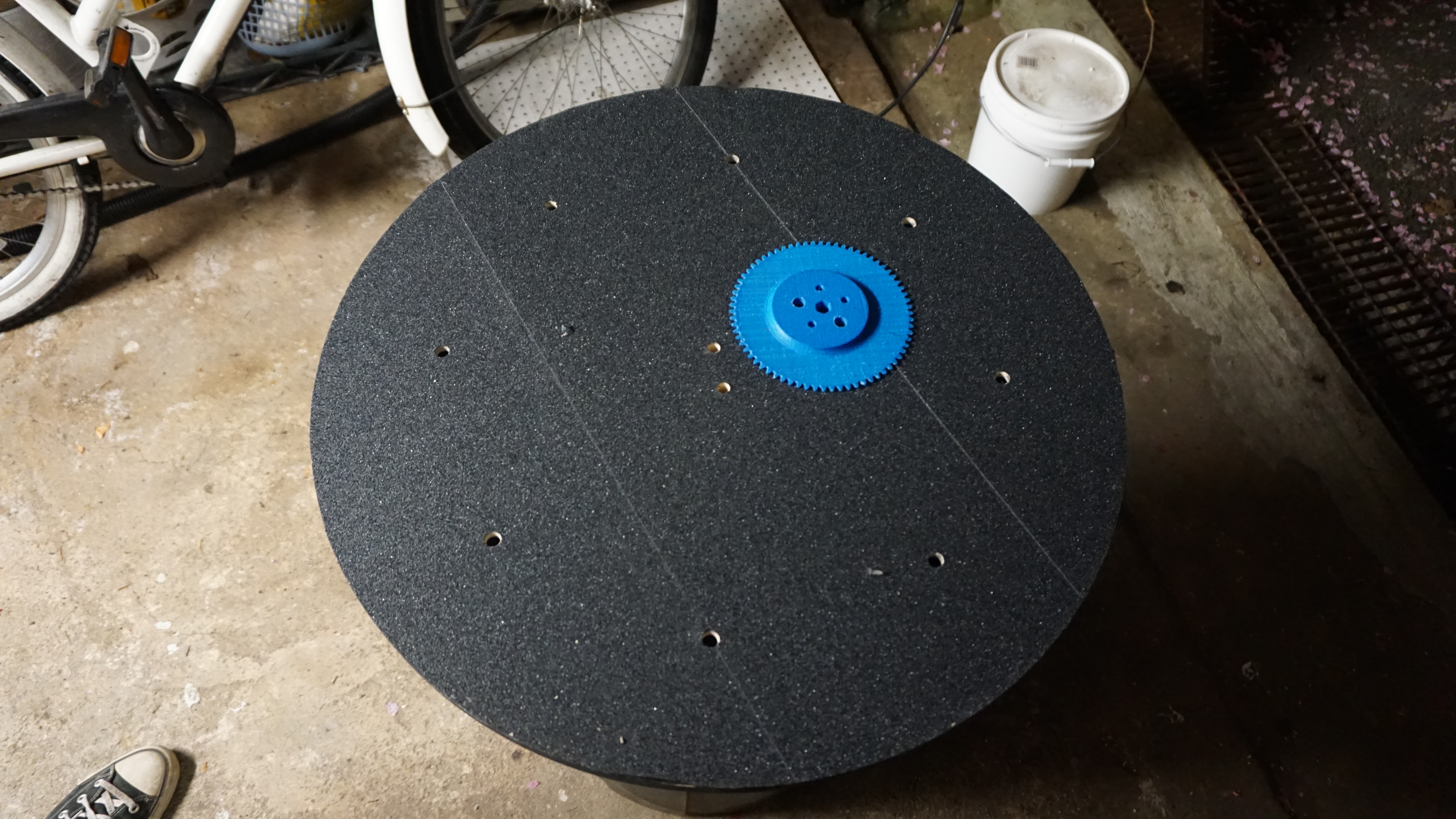
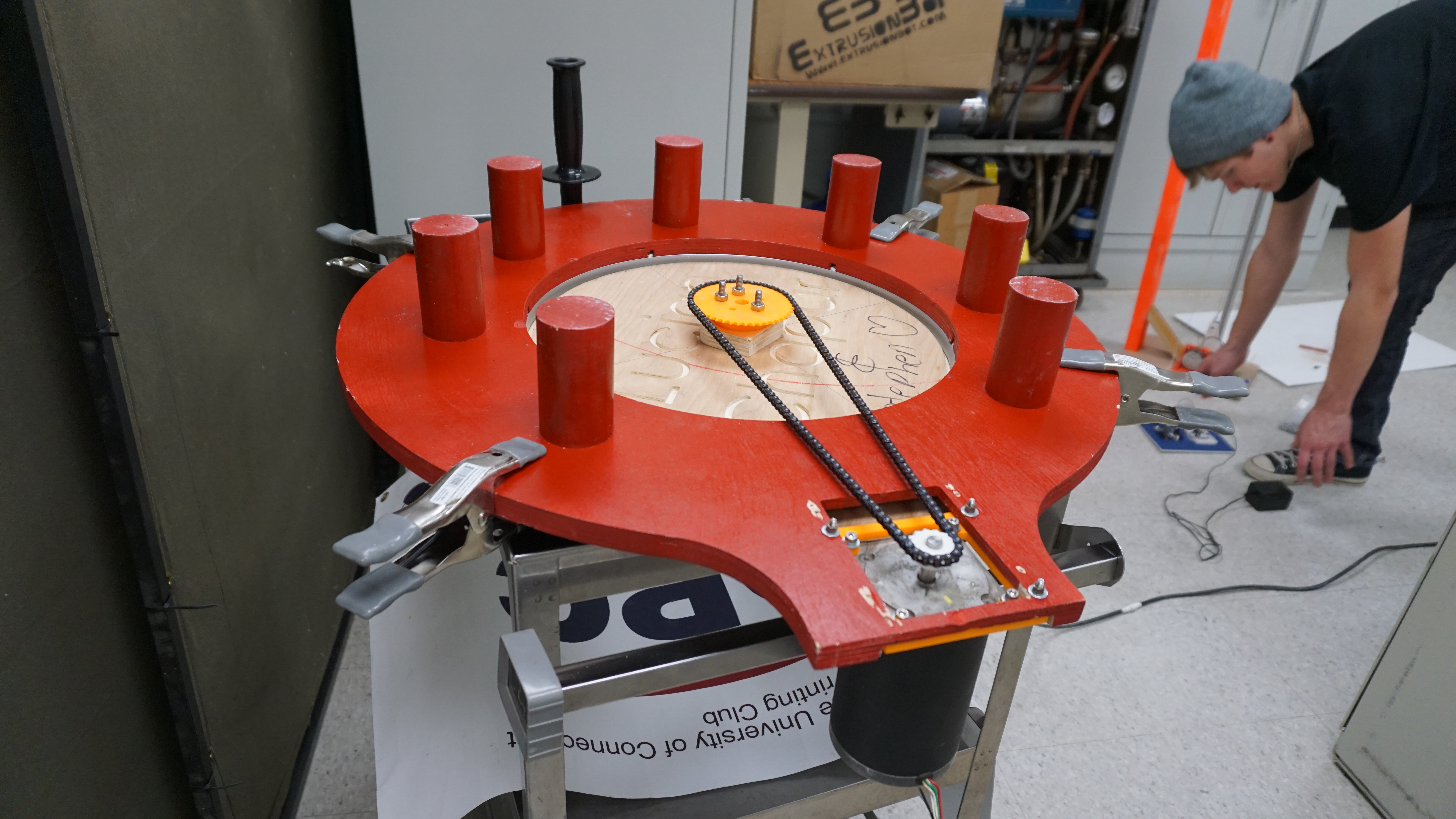 The bottom of the pedestal with 3D printed sprockets in white and orange
It ended up working great, and the rotation was consistent enough that we could just run the motor for a set amount of time and get pretty close to a full rotation. Plenty accurate for Skanect to maintain tracking.
 Movin’!
We tidied up some of the wiring and attached the control panel to the base of the tower for a cleaner experience.
Testing
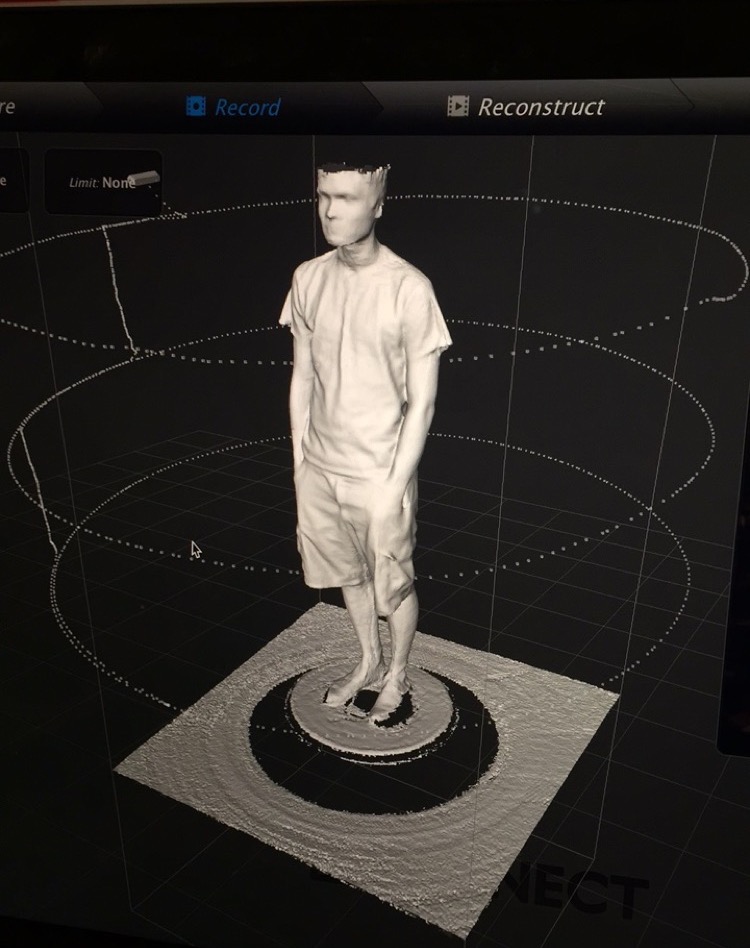
Now that the bulk of the work was complete, we started running tests and things were looking promising. Below is a scan of me, and it’s one of the first scans run on the machine. The three circles around the model show the path that the Kinect took relative to me.
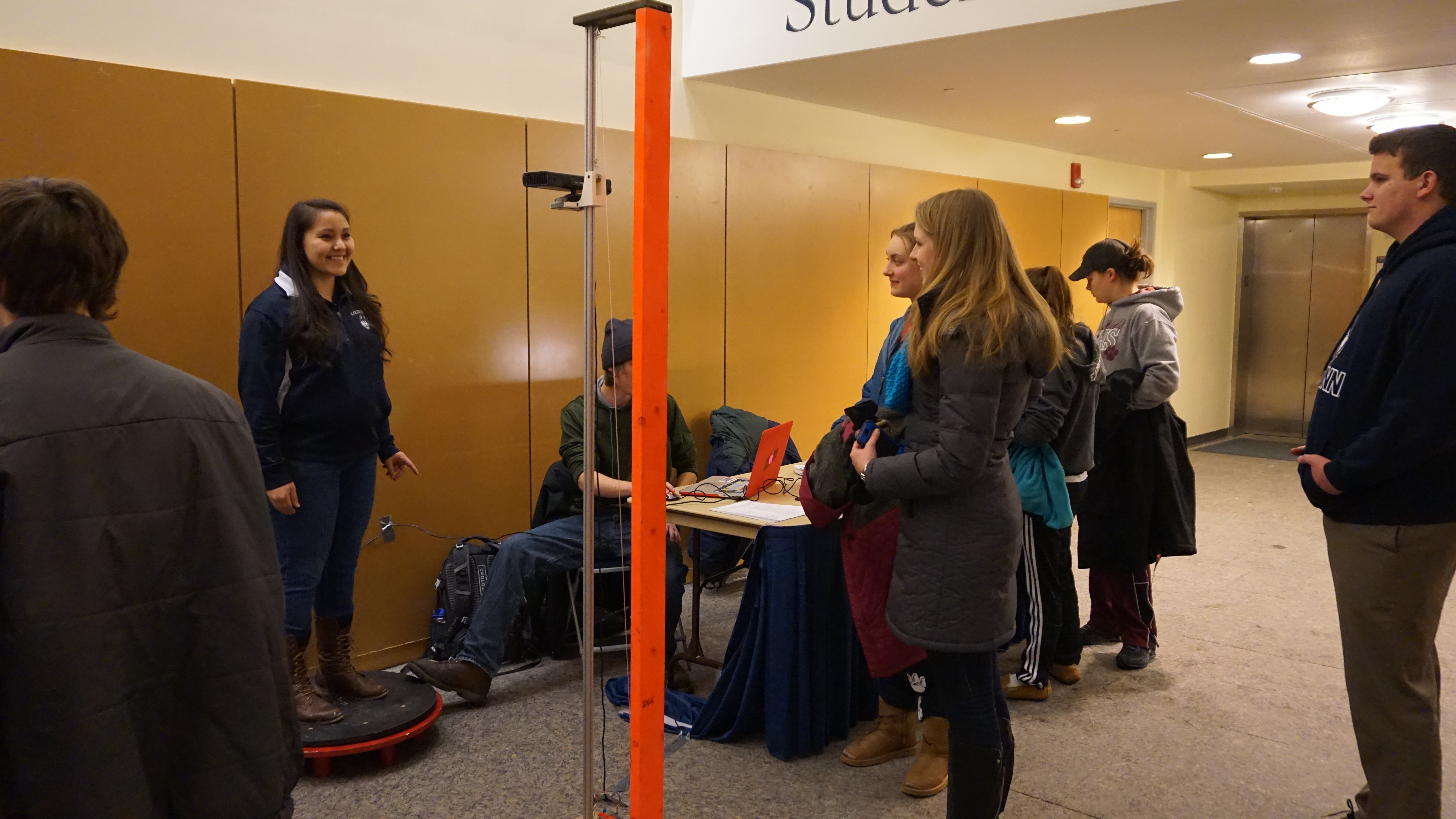
Then Lucy took the scanner to an event at the UConn Student Union and scanned a ton of students, gathering information about what we could improve before shipping.
I also scanned my roommates and assembled a tiny roomie crew.
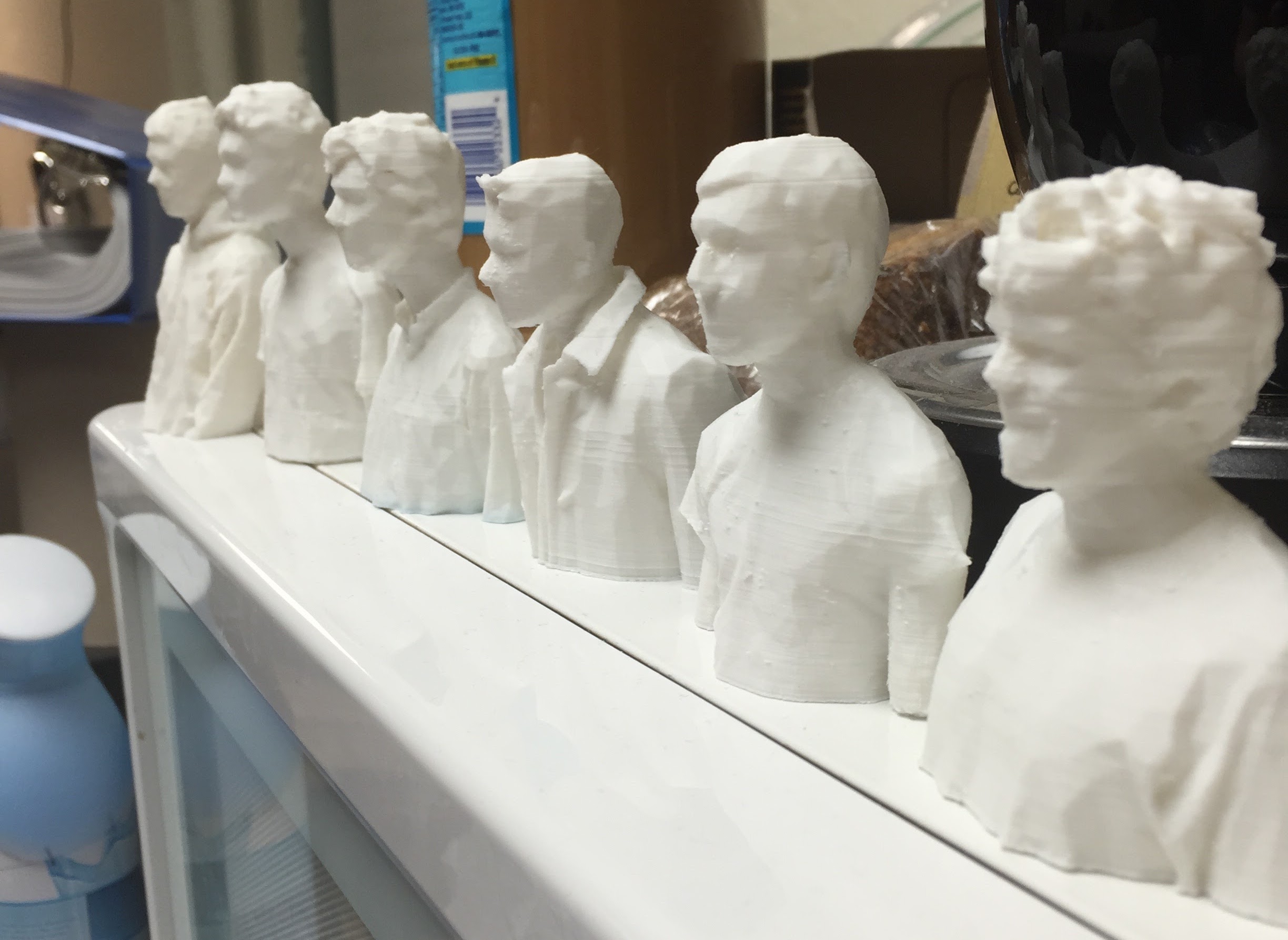 Tiny Roomies: ASSEMBLE
The scanner worked, but there were a few things to tweak before we were ready to ship. Lucy and I brought the scanner down to his house a couple weeks before our delivery date and had a hackathon finishing up the loose ends.
Tweaks
Based on feedback from the UConn event, we knew we had to improve the pedestal. The chain kept coming off of the sprockets, and the top surface was a bit slippery for a moving platform.
We solved the slip issue with some griptape! A few sheets made the pedestal feel more stable and look quite nice.
For the chain issue, we did a couple things. We printed a bigger, beefier sprocket that would have more tooth engagement, and Lucy added a whole tensioning system.
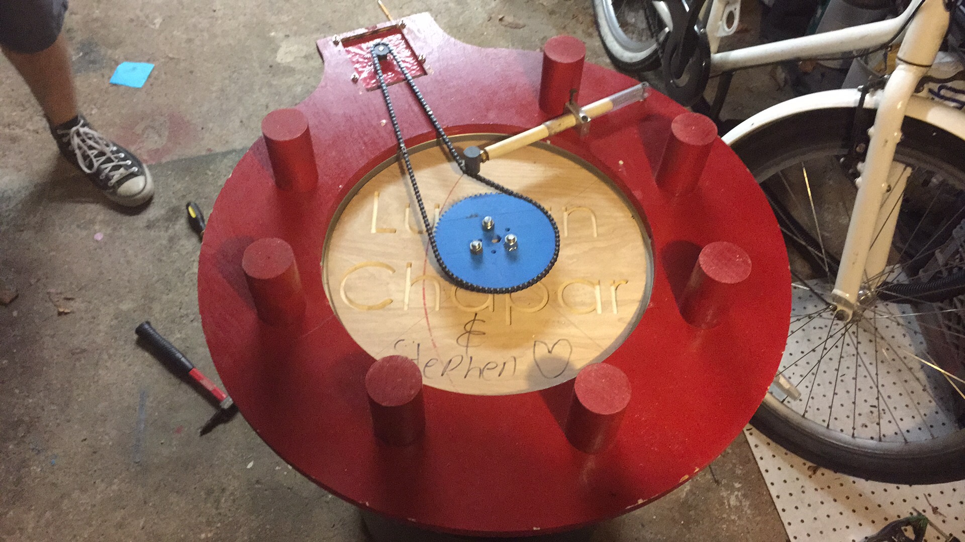
The previous version just had the motor mounted in a slotted hole pattern so we could pull it tight. However, the sprockets weren’t perfectly concentric with the axis of rotation, so we had to deal with varying sprocket spacing. We didn’t have time to recut the pedestal more precisely, so Lucy added a variable tensioning rod that applied constant pressure to the chain, regardless of the slack introduced.
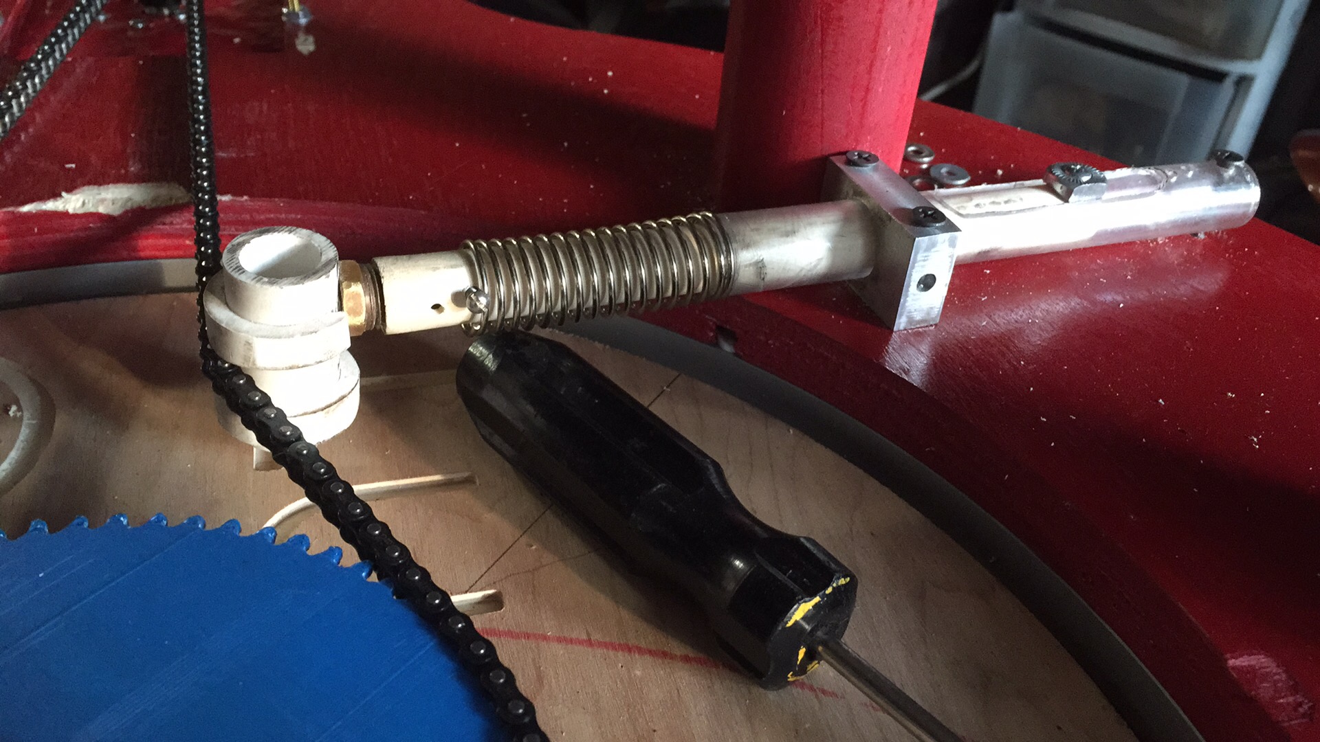
This did wonders for the pedestal’s reliability.
We also had some improvements to make on the tower. We gave the whole thing a nice paint job, and properly mounted the electronics into the base. Lucy even added a heatsink to the stepper, which we found could get a bit toasty after running many scans in a row.
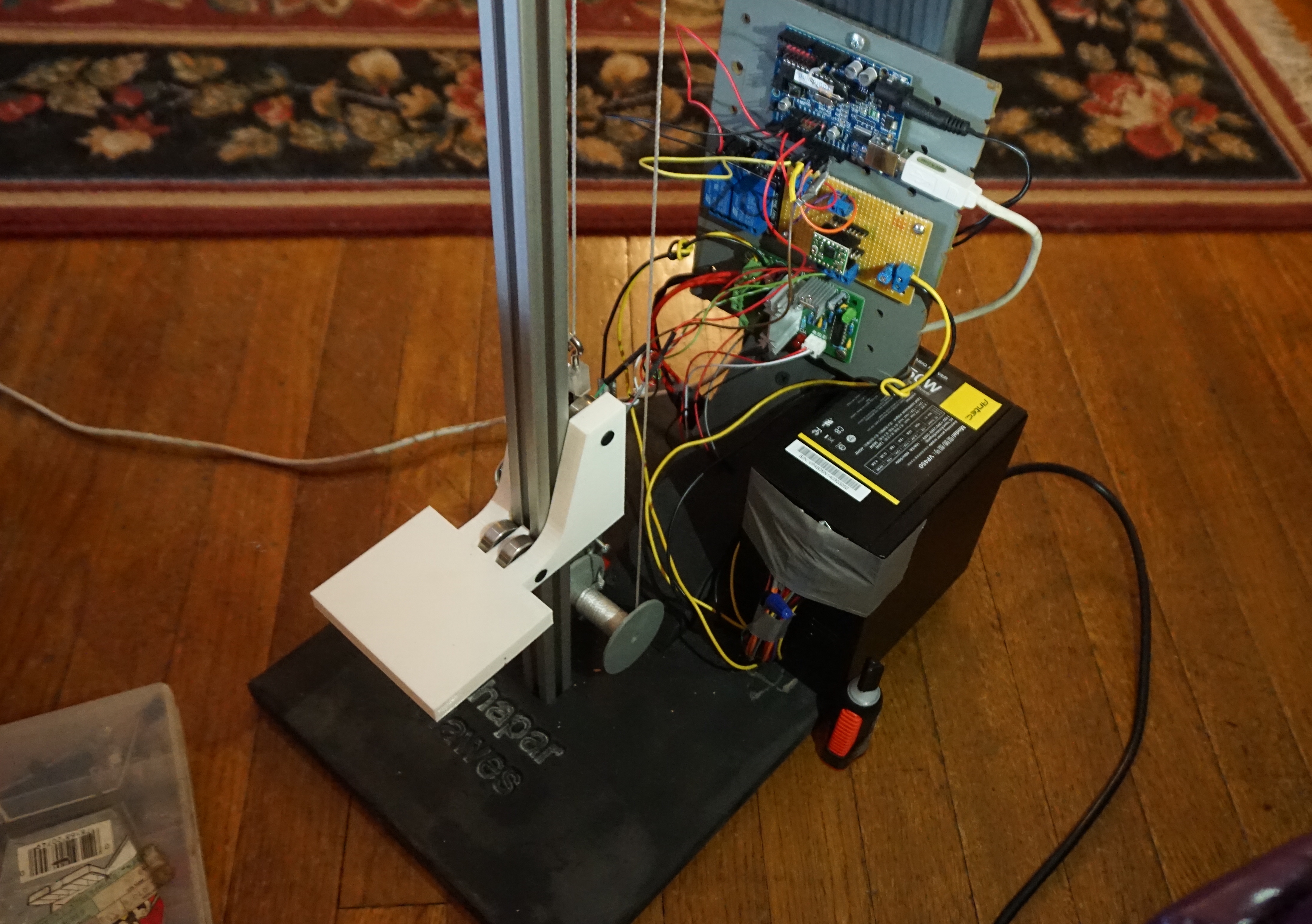
Then we enclosed all the controls with some ply and a removable polystyrene cover so it looked a bit neater.
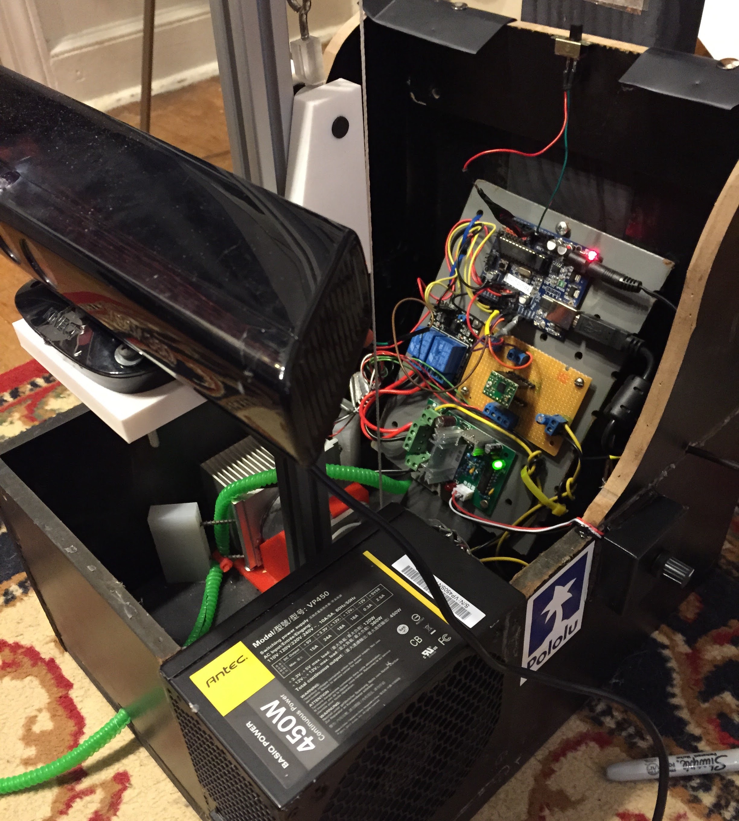
Then it was running dozens of tests, and looking for bugs.
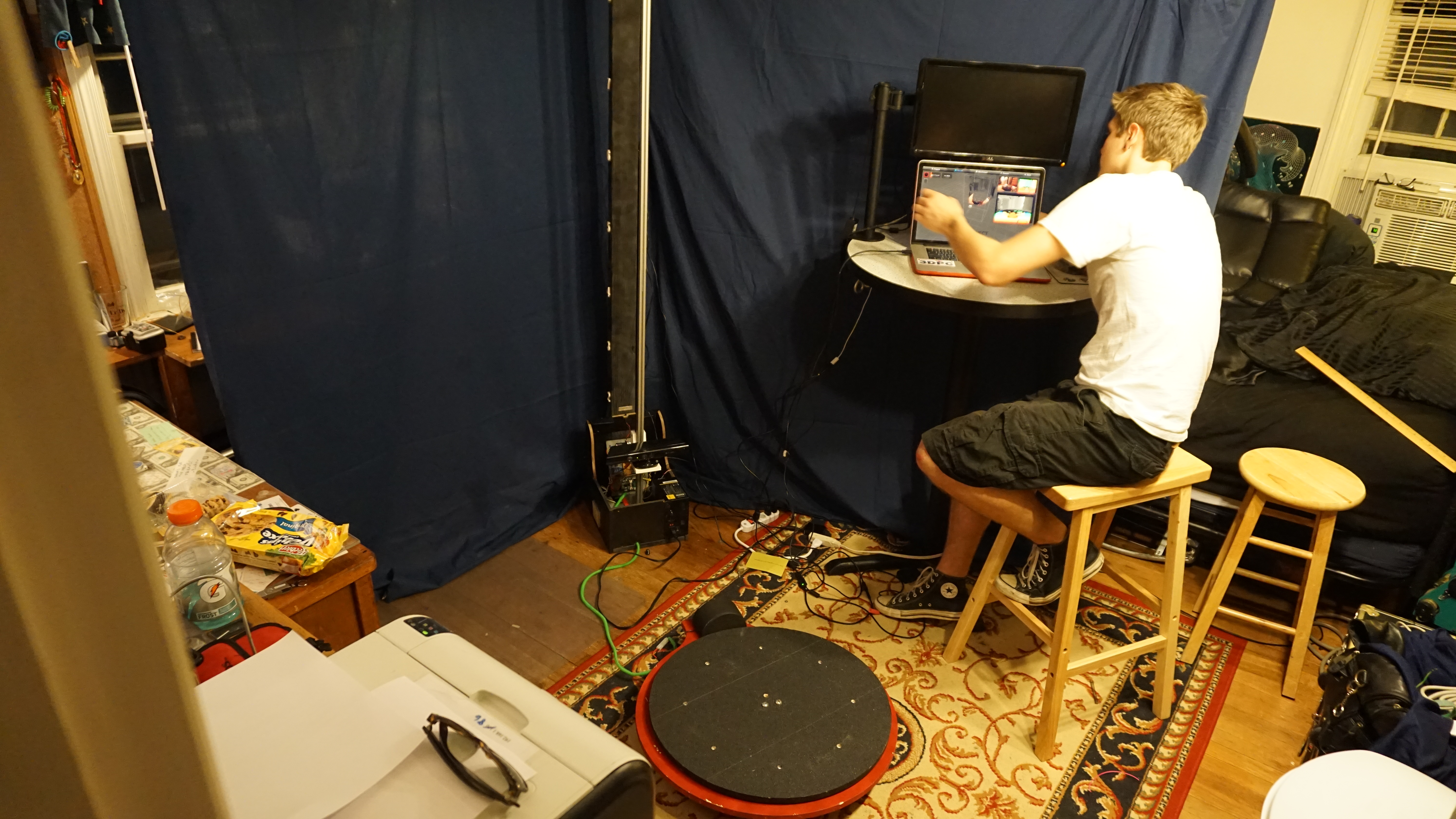 Running some tests in Lucy’s bedroom the night before shipping
Delivery
After a quick drive to the install site, setup was smooth!
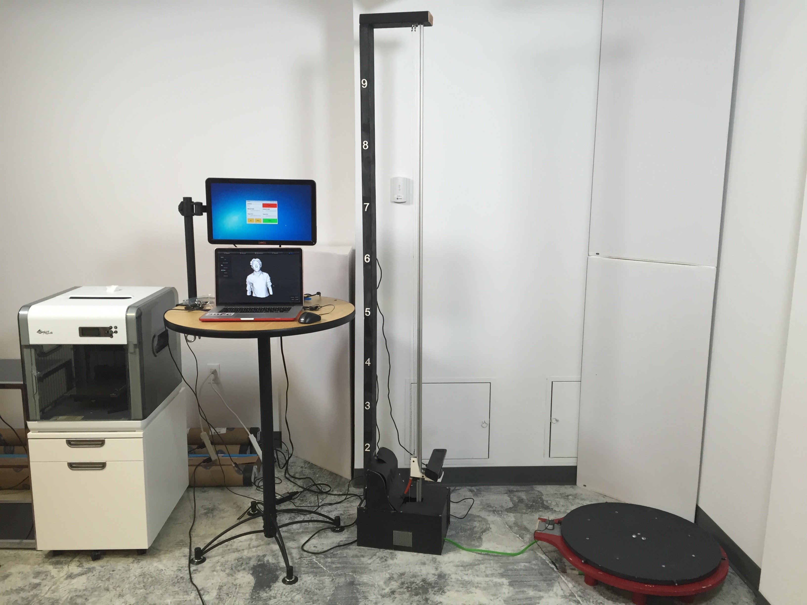 All set up next to the facility’s 3D printer
 First scan on location!
 Shipped 😎
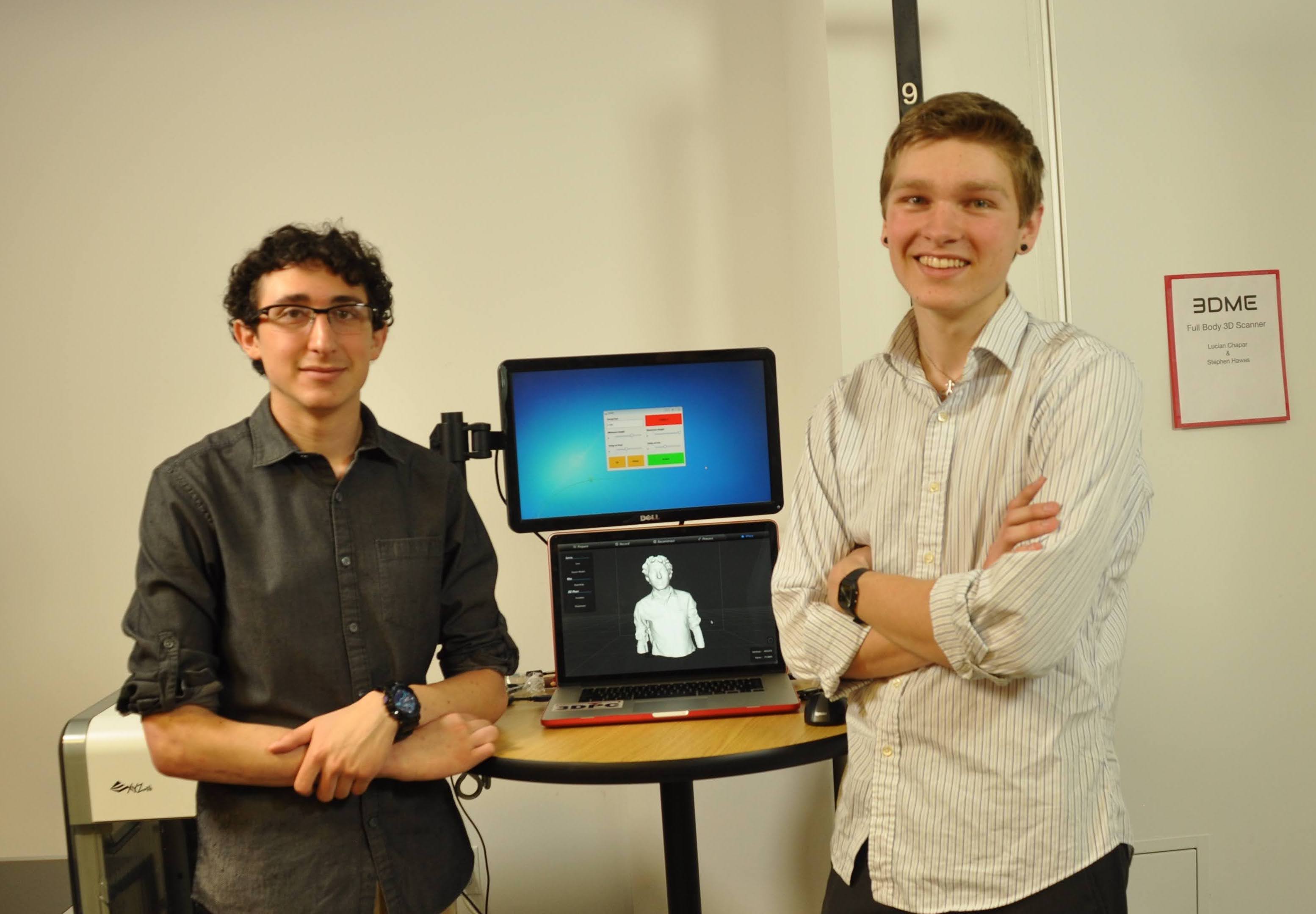
We were stoked. It was a great day delivering a project that pushed both Lucy and myself to learn new skills, deal with deadlines and budgets, and work on projects in a team.
Lucy and I made a bit of money from the sale, which I put directly into my Lulzbot Taz 5, and she invested in an XCarve CNC machine.